


You are using an out of date browser. It may not display this or other websites correctly.
You should upgrade or use an alternative browser.
You should upgrade or use an alternative browser.
Tom Senior M1 renovation/servicing
- Thread starter brewdexta
- Start date
brewdexta
The biggest tool in the box
- Messages
- 5,815
- Location
- UK
Commissioning
After clearing some space for the M1, I finally got around to start commissioning.
Stage 1 is getting it powered up.
First I went around and topped up all the oiling points and the 2 grease nipple (two on the motor and one on the knuckle head). The oil point in the head spindle inside the main body didnt take as much oils as I expected.
I then checked all the belts and disconnected the suds pump, I'll test that later.
Next I mounted the VFD, its a Allen & Bradley Poweflex 40 with the start/stop and speed control taken out to a pot hidden inside an old start/stop box as shown earlier in the thread. I mounted the VFD on a steel plate using rivnuts as shown below, I could only find some clear matt lacquer in my old aerosol bin so gave it a coat of that. It's resting on the bed of the other mill I have in bits.
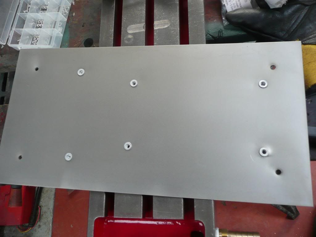
I then screwed it to the insulated steel panelling. I probably shouldn't do for insurance purposes so may move it. The two rivnuts below the VFD is to mount some strain relief mechanism for the cables.
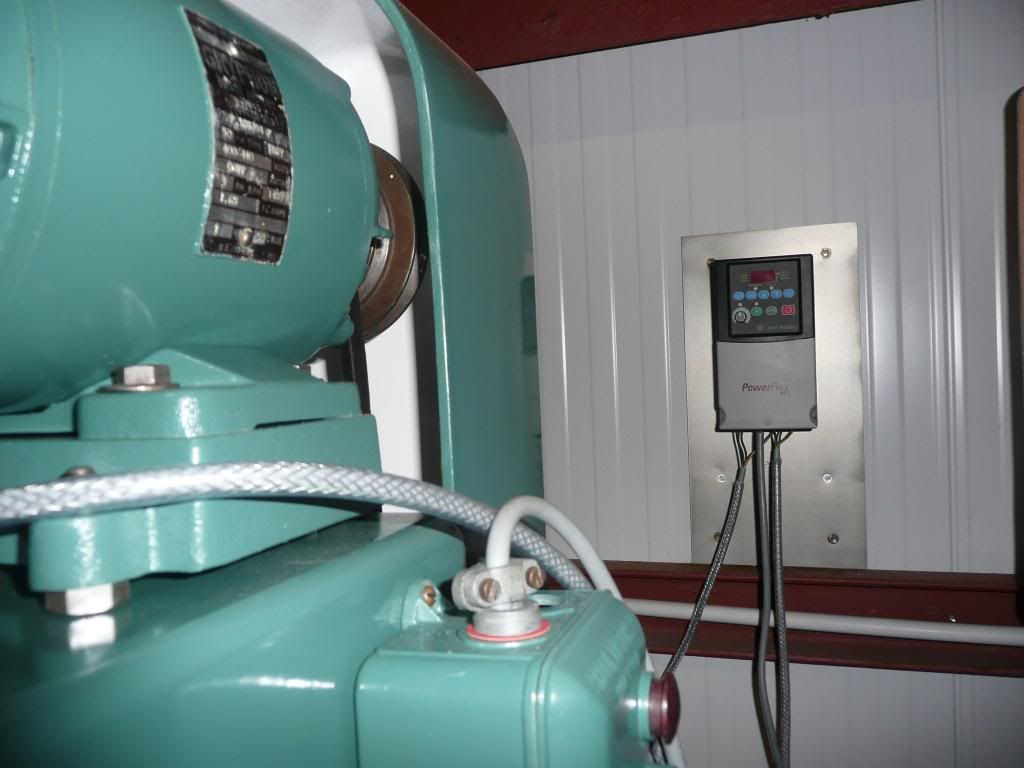
I did a double check of all the cabling and compared it to the wiring diagrams on the manufacturers web site. I have already had it working on the bench but it only takes 10 minutes and is better than trying to return something black and crispy to the vendor
First attempt at firing it up went OK then it died However a quick check of the plug showed it was only a 3 amp fuse
  , panic over.
Next attempt was more sustained but rather slow, the variable control didn't seem to do anything. The drive belt was on the highest speed setting so moved it to the lowest, tried again and this time the speed was variable which was good but may indicate the motor is gutless or there is another issue if it can't drive the mill on the top pulley. All the pulley's are original so its not a ratio issue
The motor is probably the orginal, 1HP 3 phase, 1425 rpm Brook, I modified the windings from star to delta as shown earlier in the thread so could need the windings checking again. When I got the mill, this motor came with it but the motor fitted was a single phase 3HP motor 2800 rpm. Obviously sufficiently powerful but twice the speed it should be.
I've run out of time today but will investigate further, either it's a bit stiff somewhere (oo er missus") ) or the motor maybe fubar.
) or the motor maybe fubar.
Regards
Andy
After clearing some space for the M1, I finally got around to start commissioning.
Stage 1 is getting it powered up.
First I went around and topped up all the oiling points and the 2 grease nipple (two on the motor and one on the knuckle head). The oil point in the head spindle inside the main body didnt take as much oils as I expected.
I then checked all the belts and disconnected the suds pump, I'll test that later.
Next I mounted the VFD, its a Allen & Bradley Poweflex 40 with the start/stop and speed control taken out to a pot hidden inside an old start/stop box as shown earlier in the thread. I mounted the VFD on a steel plate using rivnuts as shown below, I could only find some clear matt lacquer in my old aerosol bin so gave it a coat of that. It's resting on the bed of the other mill I have in bits.
I then screwed it to the insulated steel panelling. I probably shouldn't do for insurance purposes so may move it. The two rivnuts below the VFD is to mount some strain relief mechanism for the cables.
I did a double check of all the cabling and compared it to the wiring diagrams on the manufacturers web site. I have already had it working on the bench but it only takes 10 minutes and is better than trying to return something black and crispy to the vendor
First attempt at firing it up went OK then it died
However a quick check of the plug showed it was only a 3 amp fuse , panic over.Next attempt was more sustained but rather slow, the variable control didn't seem to do anything. The drive belt was on the highest speed setting so moved it to the lowest, tried again and this time the speed was variable which was good but may indicate the motor is gutless or there is another issue if it can't drive the mill on the top pulley. All the pulley's are original so its not a ratio issue
The motor is probably the orginal, 1HP 3 phase, 1425 rpm Brook, I modified the windings from star to delta as shown earlier in the thread so could need the windings checking again. When I got the mill, this motor came with it but the motor fitted was a single phase 3HP motor 2800 rpm. Obviously sufficiently powerful but twice the speed it should be.
I've run out of time today but will investigate further, either it's a bit stiff somewhere (oo er missus
Regards
Andy
- Messages
- 24,403
- Location
- Birmingham
Hope you're going to tidy the wiring up?, the terminals are carrying the weight of the cables at present  if the VFD doesn't have a gland plate in the bottom, mount a small adaptable box directly underneath.
Use the correct glands so the braiding is earthed.
if the VFD doesn't have a gland plate in the bottom, mount a small adaptable box directly underneath.Use the correct glands so the braiding is earthed.
brewdexta
The biggest tool in the box
- Messages
- 5,815
- Location
- UK
Hope you're going to tidy the wiring up?, the terminals are carrying the weight of the cables at present
Use the correct glands so the braiding is earthed.
I put the two rivnuts under the VFD for a strain relief machanism. Both this VFD and my Mistubishi VFD I use on the lathe don't have any mechanism for doing this, just some slots. I think they fit into a case of some descriiption that does provides that function, I'm not entirely sure.
I will route the cables upwards and then down to the VFD so you can get around the mill without interference. I aslo made sure I bought cables with screens so will be earthing them too.
Usually if I get ahead of myself and put it all in before testing, something goes pair shaped and I have to rip it out again, I thought I would give it a bit of a test first
 Its possible that I have to replace the motor so glad I didn't put all the clips and things in too soon.
Cheers
Andy
brewdexta
The biggest tool in the box
- Messages
- 5,815
- Location
- UK
Hi Ronan, I'm pretty sure it is as the motor label is legible and I bought the inverter to suit and took the motor to bits but I'm working away from home so can't double check today. However now you have asked and put the seed of doubt in my mind I'll have to check when I get back 
Cheers
Andy
Cheers
Andy
I have a tom senior with a similar leak where the drive shaft enters the table, does anyone have suggestions how to fix that??I've only done odds and sods to this recently, nearly finished, just need to take the bed off again to see if I can fix the leak from the universal joint where the power feed shaft meets the carriage, turn up a better bush for the motor pulley, finish off the grills for the suds drain then adjust everything up and grease/oil the various bit.
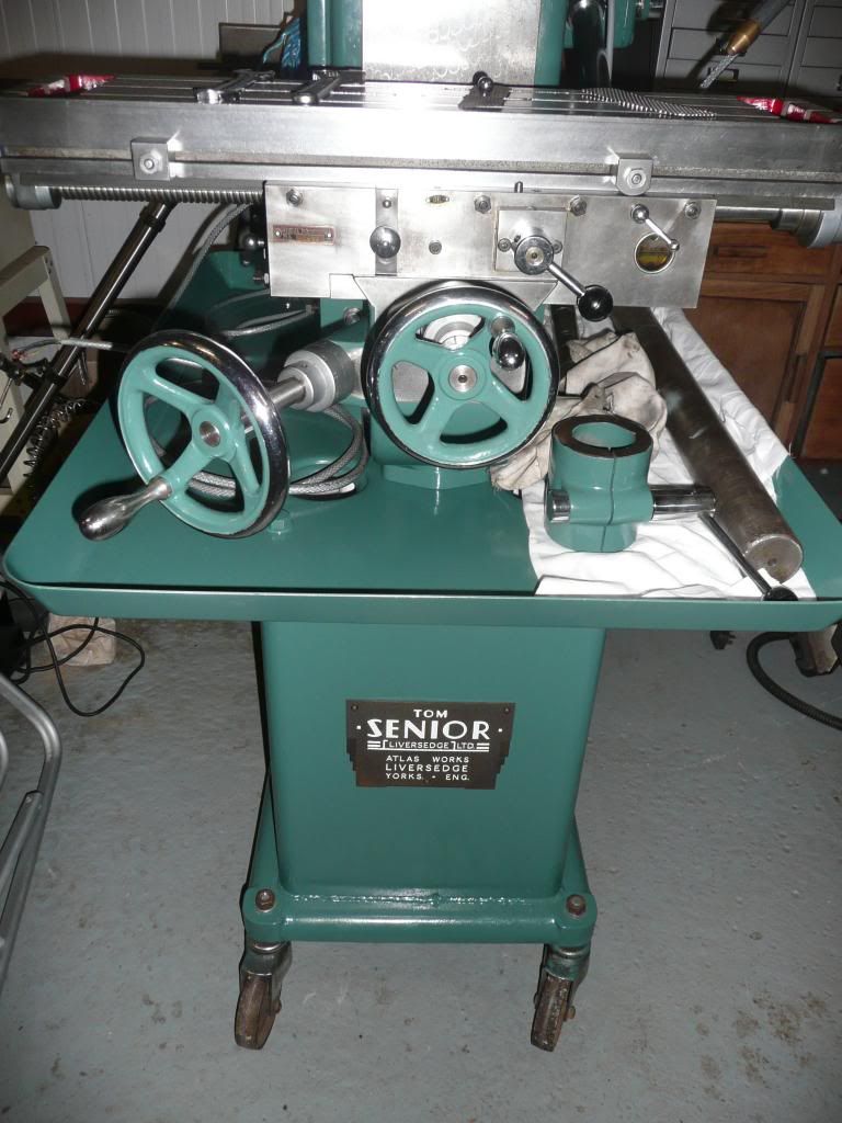
I'm going to move my morticing machine further down the workshop and place the in its place, I rarely use the morticer but I have a got a couple of jobs planned for it. I was keeping one side of the workshop for wood working and one for metal but the metal side of things seem to be taking over!
Here's the badge back on.
Cheers
Andy
Steve
Dieselman 63
Forklift Certified
- Messages
- 5,888
- Location
- Wellington, New Zealand
Chicken head knob? It's not an insult
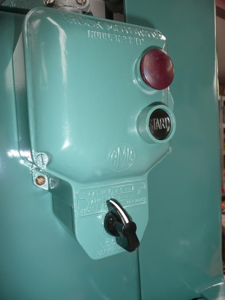
You want to get a tinlet of Humbrol 34 (or any white enamel paint) and dab those 'start' letters with paint - too much is good, then wipe the excess off with a clean rag. It makes them look brand new and it's amazing how much it 'lifts' the look of the machine
")
brewdexta
The biggest tool in the box
- Messages
- 5,815
- Location
- UK
It's 12 years since I finished the mill, so probably time for an update
I've posted a few times about issues with the motor on the mill in several general threads. The original motor is 1hp and is struggling a bit, I don't believe it's kicking out 1hp presently.
So I've decided to upgrade to motor intended for VFD use and double the power to 2hp, mainly so I don't need to change gears.
Here's the original motor on its cast iron base.

The base then stands on double ended studs so you can adjust the height to tension the belt. Here are the bolts with a steel plate and the new motor balanced on top, just as a dry run.

The problem is that the new motor's feet will interfere with the adjusting bolts, both sides on.

And end on.

The good news is that the belt cover will fit.

Here's a more general view.

So far, the plan is to use the original cast iron plate to avoid the clash of bolts, and use the new steel plate on top of it ,using the original motor bolt spacing to hold it down. The new steel plate will be trimmed in length a little. This way I can still tension the belt.
I'll do another dry run tomorrow with this arrangement before deciding.
I've posted a few times about issues with the motor on the mill in several general threads. The original motor is 1hp and is struggling a bit, I don't believe it's kicking out 1hp presently.
So I've decided to upgrade to motor intended for VFD use and double the power to 2hp, mainly so I don't need to change gears.
Here's the original motor on its cast iron base.
The base then stands on double ended studs so you can adjust the height to tension the belt. Here are the bolts with a steel plate and the new motor balanced on top, just as a dry run.
The problem is that the new motor's feet will interfere with the adjusting bolts, both sides on.
And end on.
The good news is that the belt cover will fit.
Here's a more general view.
So far, the plan is to use the original cast iron plate to avoid the clash of bolts, and use the new steel plate on top of it ,using the original motor bolt spacing to hold it down. The new steel plate will be trimmed in length a little. This way I can still tension the belt.
I'll do another dry run tomorrow with this arrangement before deciding.
brewdexta
The biggest tool in the box
- Messages
- 5,815
- Location
- UK
I just remembered @Smouser post regarding sliding motor bases.
Post in thread 'New motor for lathe' https://www.mig-welding.co.uk/forum/threads/new-motor-for-lathe.144068/post-2598436
These sound ideal instead of the steel plate as it allows me to fine tune the belt alignment without cutting slots in the 10mm plate.
I'll get one ordered as well as some sliding motor rails, I've never been able to correctly tension the Rapidor donkey saw belt sufficiently.
brewdexta
The biggest tool in the box
- Messages
- 5,815
- Location
- UK
Like a lot of lathes, hinge the plate one side, mounted on two of the existing mill bolt holes. Make a swivelling bracket to hold a length of studding mounted on the other two holes.
I did consider something like that but the two front mounting holes would still clash with the motor mounting holes, but I may not be thinking about it the same way as yourself. I think I'll take a punt on a motor slide base first, looking at the dims it should fit fine and give me for/aft movement to align the pulleys. If it doesn't work then I'll use it on the donkey saw motor and think again.
This is the cast base that the original motor sat on, unfortunately too narrow for a 90L frame motor feet without a plate on top. But if I bolt the sliding motor base to that, then I should be good to go. Alternatively, I could bolt the sliding base directly to the adjusters holding the cast base. I'll get the sliding base first and think about it. Its been about 2 years since I took the motor off so another couple of weeks won't hurt
brewdexta
The biggest tool in the box
- Messages
- 5,815
- Location
- UK
The sliding motor plate arrived, looks OK.

The motor needs to go back about 20mm or so, there's plenty of adjustment.

A bit more than a dry run as I had to drill some holes to match up with the existing studs.

Unfortunately they needed to be just where there is a bevel. I'll make up some angle washers.
The motor needs to go back about 20mm or so, there's plenty of adjustment.
A bit more than a dry run as I had to drill some holes to match up with the existing studs.
Unfortunately they needed to be just where there is a bevel. I'll make up some angle washers.
brewdexta
The biggest tool in the box
- Messages
- 5,815
- Location
- UK
The motor plate worked, still not much room for longer bolts but managed to select the correct swear words in the correct order and then it went together fine. I managed to reuse the existing belt, I thought I would run out of adjustment being a bigger frame motor but it worked fine. The fore/aft adjustment on the motor plate meant that lining ul the top and bottom pulleys was a doddle.
Next job was strain relief for the cables going to the VFD. I uses a bit of 25mm thick HDPE sheet.

It's a sod to cut, the bandsaw is a bit fast so it tends to start melting a little, but taking it steady it went through it OK.
.jpg")
The idea is to drill holes the same size as the diameter of the mains, motor and control cables, then cut across the holes, the kerf of the bandsaw means that it will tighten down on the cables. The pic above demonstrates.

VFD mounted, complete with brake resistor and strain relief block. I need to tidy the cabling up a bit. It took me a while to realise that the factory reset of the VFD parameters put some parameters in the 3rd and 4th analogue inputs that clashed with the start/stop parameters I had in the first and second. It all works now from the old switch controls including speed control. The cold plate VFD is silent, which is really nice, I hate fans. I need to configure the braking resistor parameters, I haven't done that before on a WEG but doesn't look difficult.
I'm going to give the mill a bit of spit and polish and a full test next week, I've got family commitments this week that will keep me out of the workshop.
Next job was strain relief for the cables going to the VFD. I uses a bit of 25mm thick HDPE sheet.
It's a sod to cut, the bandsaw is a bit fast so it tends to start melting a little, but taking it steady it went through it OK.
The idea is to drill holes the same size as the diameter of the mains, motor and control cables, then cut across the holes, the kerf of the bandsaw means that it will tighten down on the cables. The pic above demonstrates.
VFD mounted, complete with brake resistor and strain relief block. I need to tidy the cabling up a bit. It took me a while to realise that the factory reset of the VFD parameters put some parameters in the 3rd and 4th analogue inputs that clashed with the start/stop parameters I had in the first and second. It all works now from the old switch controls including speed control. The cold plate VFD is silent, which is really nice, I hate fans. I need to configure the braking resistor parameters, I haven't done that before on a WEG but doesn't look difficult.
I'm going to give the mill a bit of spit and polish and a full test next week, I've got family commitments this week that will keep me out of the workshop.
Guineafowl
Member
- Messages
- 1,549
- Location
- Nairn
I can’t find a decent guide to calculating brake resistor size and wattage, do you know of one?The motor plate worked, still not much room for longer bolts but managed to select the correct swear words in the correct order and then it went together fine. I managed to reuse the existing belt, I thought I would run out of adjustment being a bigger frame motor but it worked fine. The fore/aft adjustment on the motor plate meant that lining ul the top and bottom pulleys was a doddle.
Next job was strain relief for the cables going to the VFD. I uses a bit of 25mm thick HDPE sheet.
View attachment 502318
It's a sod to cut, the bandsaw is a bit fast so it tends to start melting a little, but taking it steady it went through it OK.
View attachment 502317
The idea is to drill holes the same size as the diameter of the mains, motor and control cables, then cut across the holes, the kerf of the bandsaw means that it will tighten down on the cables. The pic above demonstrates.
View attachment 502319
VFD mounted, complete with brake resistor and strain relief block. I need to tidy the cabling up a bit. It took me a while to realise that the factory reset of the VFD parameters put some parameters in the 3rd and 4th analogue inputs that clashed with the start/stop parameters I had in the first and second. It all works now from the old switch controls including speed control. The cold plate VFD is silent, which is really nice, I hate fans. I need to configure the braking resistor parameters, I haven't done that before on a WEG but doesn't look difficult.
I'm going to give the mill a bit of spit and polish and a full test next week, I've got family commitments this week that will keep me out of the workshop.
Also, they’re expensive, so could you use something simple like a kettle element?
brewdexta
The biggest tool in the box
- Messages
- 5,815
- Location
- UK
I just used the size recommended by Inverter Drive Supermarket where I bought the motor and inverter from. There are some calcs on the page for each resistor so you could probably work it out.
brewdexta
The biggest tool in the box
- Messages
- 5,815
- Location
- UK
I only had an hour in the workshop today, so decided to do a spot of tidying up. Part of the reason it is so messy is that I have lots of part finished jobs, so decided to finish one off so I can get it out of the way, its only been kicking around for 8 years....
I rough cut these two bits of SS perforated sheet 8 years ago, today I trimmed them to fit and added the brass knob.

It's to solve this problem, swarf getting into the return to the suds tank.

Not my idea, the M1 came with a very crusty one, but the knob clashed with the central T slot as it was in the middle.
These have a patented offset knob to avoid that
The Light vertical

And the M1
I rough cut these two bits of SS perforated sheet 8 years ago, today I trimmed them to fit and added the brass knob.
It's to solve this problem, swarf getting into the return to the suds tank.
Not my idea, the M1 came with a very crusty one, but the knob clashed with the central T slot as it was in the middle.
These have a patented offset knob to avoid that
The Light vertical
And the M1


