- Forums
- Tools, Compressors and Metal Coatings
- Tools, Materials and Techniques
- Machining
- Lathes and other Machining Equipment
You are using an out of date browser. It may not display this or other websites correctly.
You should upgrade or use an alternative browser.
You should upgrade or use an alternative browser.
Tos FN22 milling machine (Deckel clone)
- Thread starter Pete.
- Start date
pressbrake1
Member
- Messages
- 5,553
- Location
- Essex
My pleasure @Pete.So I had a bit of time today to take a look at this table which was planed a few weeks ago. I actually have been off work since the 3rd but we have done a marathon of DIY/decorating which is only now finished.
I set up a dial gauge to measure how parallel the ways were. These are very difficult to scrape coz of the overhanging ledge, you can't get a biax in there and if you hand scrape it you can't see what you're doing, so it needed to be good.
And it is good, that is a ten-thousandths reading dial gauge so each number is just one thou. It's nice and parallel all along the length. Big thanks to @pressbrake1
The fresh fish chips you got for lunch was a lovely surprise!
paradipiro
Member
- Messages
- 109
- Location
- Budapest, Hungary
Dear Gents,
I have an FN 22 milling machine for around 3 yers or so, but I just got to the point, that I want to dismantle the main parts, for mostly cleaning purposes.
As i go further inside the Beast, I find more and more things to do, completely normal phenomenon, we all know.
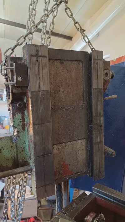
Blocked oiling routes, worn out parts, mostly leadscrews and nuts, the ways..
Today I dismantled the attached table, the cross table, and the vertical support of the table.
As i saw before, @Pete. does a magnificent work on his machine, I'm just try to find my jaw, 'cause is's dropped, and I have no clure where it is right now.
The X axis nut on my machine is a single piece, cast iron one (worn out), I think its not original. Pete, if you could make a drawing about yours, I could copy back the original design hopefully.
I will need to do new X screw also, because the middle section is terribly worn out.
The Z axis nut and screw seems to be original to me, but I got stuck with the dismantling process of the vertical support piece. The Z screw and feed shaft won't come out, so I could measure the end of the Z leadscrew.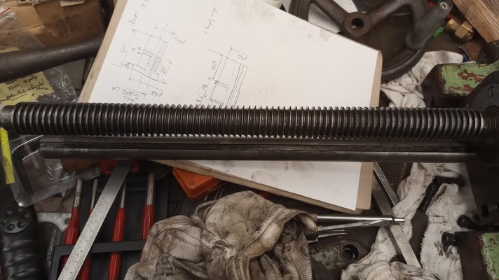
My poor little machine have seen better days.. The previous owner greased EVERYTHING on this little fella, so now I cannot figure out, how to disassemble that part.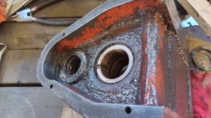
For better understanding the scale: I removed around 500 ccm grease from the bucket around the Z handle shaft. So it really needs a good cleaning.
Pete, or anyone else, if you have some drawings of the leadscrews, and nuts of this machine, please help me.
Thanks in advance!
I have an FN 22 milling machine for around 3 yers or so, but I just got to the point, that I want to dismantle the main parts, for mostly cleaning purposes.
As i go further inside the Beast, I find more and more things to do, completely normal phenomenon, we all know.

Blocked oiling routes, worn out parts, mostly leadscrews and nuts, the ways..
Today I dismantled the attached table, the cross table, and the vertical support of the table.
As i saw before, @Pete. does a magnificent work on his machine, I'm just try to find my jaw, 'cause is's dropped, and I have no clure where it is right now.
The X axis nut on my machine is a single piece, cast iron one (worn out), I think its not original. Pete, if you could make a drawing about yours, I could copy back the original design hopefully.
I will need to do new X screw also, because the middle section is terribly worn out.
The Z axis nut and screw seems to be original to me, but I got stuck with the dismantling process of the vertical support piece. The Z screw and feed shaft won't come out, so I could measure the end of the Z leadscrew.

My poor little machine have seen better days.. The previous owner greased EVERYTHING on this little fella, so now I cannot figure out, how to disassemble that part.

For better understanding the scale: I removed around 500 ccm grease from the bucket around the Z handle shaft. So it really needs a good cleaning.
Pete, or anyone else, if you have some drawings of the leadscrews, and nuts of this machine, please help me.
Thanks in advance!
Pete.
Forum Supporter
- Messages
- 15,055
- Location
- Kent, UK
Dear Gents,
I have an FN 22 milling machine for around 3 yers or so, but I just got to the point, that I want to dismantle the main parts, for mostly cleaning purposes.
As i go further inside the Beast, I find more and more things to do, completely normal phenomenon, we all know.
View attachment 380902
Blocked oiling routes, worn out parts, mostly leadscrews and nuts, the ways..
Today I dismantled the attached table, the cross table, and the vertical support of the table.
As i saw before, @Pete. does a magnificent work on his machine, I'm just try to find my jaw, 'cause is's dropped, and I have no clure where it is right now.
The X axis nut on my machine is a single piece, cast iron one (worn out), I think its not original. Pete, if you could make a drawing about yours, I could copy back the original design hopefully.
I will need to do new X screw also, because the middle section is terribly worn out.
The Z axis nut and screw seems to be original to me, but I got stuck with the dismantling process of the vertical support piece. The Z screw and feed shaft won't come out, so I could measure the end of the Z leadscrew.View attachment 380904
My poor little machine have seen better days.. The previous owner greased EVERYTHING on this little fella, so now I cannot figure out, how to disassemble that part.View attachment 380903
For better understanding the scale: I removed around 500 ccm grease from the bucket around the Z handle shaft. So it really needs a good cleaning.
Pete, or anyone else, if you have some drawings of the leadscrews, and nuts of this machine, please help me.
Thanks in advance!
Well you're in luck because I just dismantled the Z axis screw yesterday. You remove the circlip holding the gear at the top then tap off the gears ONE AT A TIME. Don't try to drive the screw out because it'll jam up on the keys. Remove a gear, and it's key, then the next, and key etc.
Z-axis screw, you should be able to measure but here's a quick drawing of basic sizes. Remember mine is an inch machine so it has 5TPI screws where yours is most likely metric with 5mm screw threads.
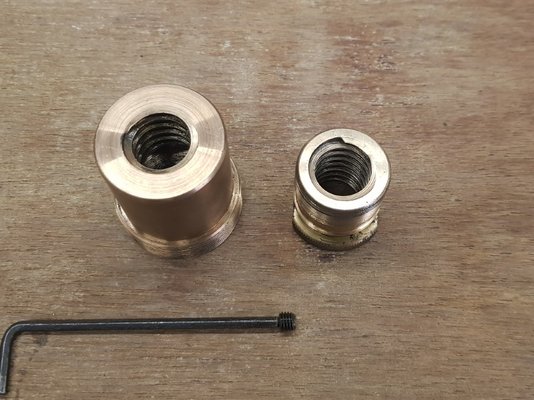
And here is the x-axis nut, which is a 2-part assembly in bronze. You would make these two parts, screw them together then thread them both at the same time for the leadscrew.
Te x-axis has a Right HAND thread, unlike the z-axis which is left hand.
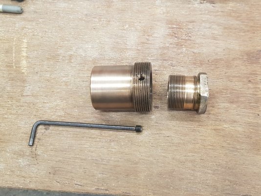
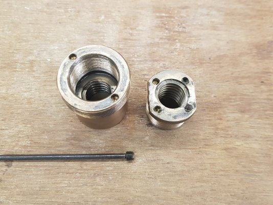
Hope this helps if you need any more info let me know.
paradipiro
Member
- Messages
- 109
- Location
- Budapest, Hungary
Yes Brad, with these machines we all know that we can only hope that the previous owners not just used these equipment, but maintained them properly.As we get into the 40th, 50th and 60th birthdays of these machines, you have to realise all of these machines, are long past their design lives and have been owned by multiple people, who may or may not be engineers. Not all machinists are engineers, and hence machines get mistreated - as you say, filled with grease.
I had no luck whet I bought this one, but its dimensions and capacity well fits into my little hobbyist machineshop. My goal is to refurbish this cutie, scrape back its geometry, and machine new x, and z screw and nut sets.
Wow! What a luck there.Well you're in luck because I just dismantled the Z axis screw yesterday. You remove the circlip holding the gear at the top then tap off the gears ONE AT A TIME. Don't try to drive the screw out because it'll jam up on the keys. Remove a gear, and it's key, then the next, and key etc.
View attachment 380920
Z-axis screw, you should be able to measure but here's a quick drawing of basic sizes. Remember mine is an inch machine so it has 5TPI screws where yours is most likely metric with 5mm screw threads.
View attachment 380921
And here is the x-axis nut, which is a 2-part assembly in bronze. You would make these two parts, screw them together then thread them both at the same time for the leadscrew.
Te x-axis has a Right HAND thread, unlike the z-axis which is left hand.
View attachment 380922
View attachment 380923
View attachment 380924
View attachment 380925
Hope this helps if you need any more info let me know.
This antibacklash nut is really interesting. Thanks for the exact measurements.
My metric one has a TR28x5 LH threaded Z screw, and an TR26x5 X screw.
See below my quick hand drawn sketch from the nuts.
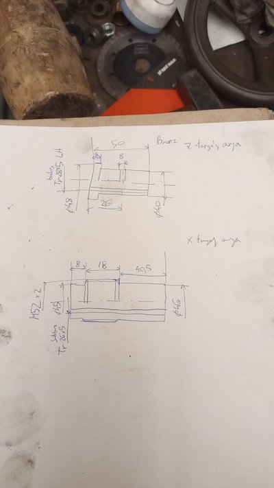
Sorry, but the comments on these drawings are in hungarian, I didn't thint I would share it internationally. I plan to make some correct drawings for the spare parts of this machine, for the future machinists.
Could you share the KEY details of the keys of the Z screw also? Thank you.
By the way I had to design back a pair of gears to the main transmission the final shaft pair had a faulty gear, which damaged the connecting one too (Z45 and Z20).
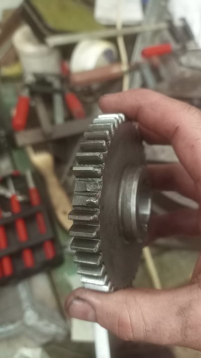
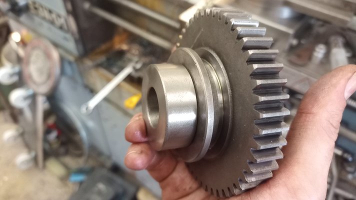
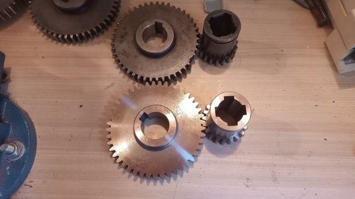
Right now they are under heat threatment. If you guys interested, I will show the results.
paradipiro
Member
- Messages
- 109
- Location
- Budapest, Hungary
Steel, beacuse if the milling tool is touching the workpiece with only one teeth, it can jump after cutting with all the backlash of the transmission link, and that makes dynamic stress on the gears. The material of the gears is 42CrMo4+QT, and after machining, they got a 0,5mm deep Nitride layer.Nice work. Are your new gears steel or cast iron?
Pete.
Forum Supporter
- Messages
- 15,055
- Location
- Kent, UK
Steel, beacuse if the milling tool is touching the workpiece with only one teeth, it can jump after cutting with all the backlash of the transmission link, and that makes dynamic stress on the gears. The material of the gears is 42CrMo4+QT, and after machining, they got a 0,5mm deep Nitride layer.
That's doing it right! I would have just used plain old steel with no treatment.
Anyway, here are your dimensions for the keyway slots. The keys are 6x6mm and 5x5mm.
paradipiro
Member
- Messages
- 109
- Location
- Budapest, Hungary
Thank you for the fast reply. Now, i can make the basic model of it, to generate the drawing. After that, i will measure and guess the original tolerances of the bearing and gear surfaces. Anyone interested in these drawings, so should I make them international, or this is just basic overthinking from me?That's doing it right! I would have just used plain old steel with no treatment.
Anyway, here are your dimensions for the keyway slots. The keys are 6x6mm and 5x5mm.
View attachment 381208
Last edited:
paradipiro
Member
- Messages
- 109
- Location
- Budapest, Hungary
I finally made some process today.
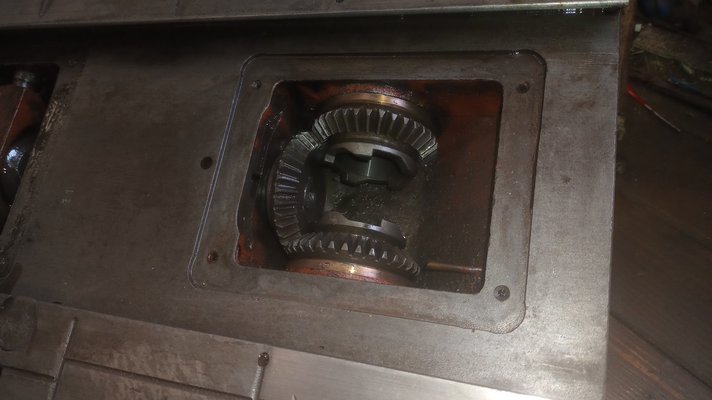
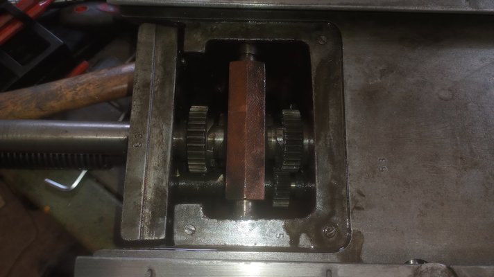
I can't figure out the next step..
The power feed shaft could not be pulled out, the key under the top gear does not fit through the bearing, and the top gear cannot get out either, because the other two gear... The shaft itself is free, it can moved a couple mm-s. I got the small screw out, what could hold it together.
paradipiro
Member
- Messages
- 109
- Location
- Budapest, Hungary
Whew!I finally made some process today.
View attachment 381807
View attachment 381808
I can't figure out the next step..
The power feed shaft could not be pulled out, the key under the top gear does not fit through the bearing, and the top gear cannot get out either, because the other two gear... The shaft itself is free, it can moved a couple mm-s. I got the small screw out, what could hold it together.
I managed to get the whole thing out. The handwheels gear should be pulled out with its bearing, so the whole gearset can be pulled down.
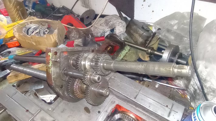
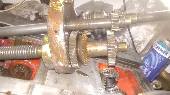
paradipiro
Member
- Messages
- 109
- Location
- Budapest, Hungary
Good job. As I said these gears you have to pull off one at a time and remove the keys to allow the next gear to come off.
View attachment 381813
Yes, i disassembled the whole thing successfully. I made some sketches, and took some measurements also. Another 0,5kg grease come out finally.

Do you have any idea about how the oil goes around inside this casting from the handpump? I will need to clean the whole route. Plan A: use compressed air, to get the goo out. Plan B: use some thin wire. I think there will be blacking screws, along the route, someone in the past must drilled it.. so these can be used for cleaning also.
Pete.
Forum Supporter
- Messages
- 15,055
- Location
- Kent, UK
By the way @paradipiro do you need any of the electrical components from the switch cabinets? I am not using the contactors from mine and I had agreed to donate them to a guy as spares but he's in Russia so that's not an option now.
paradipiro
Member
- Messages
- 109
- Location
- Budapest, Hungary
I also have these originally translated, online available manuals for this machine. The german is made with typewriter, but it has information about the complete kinematic diagram of this machine. My teachers tried to teach me german for four years, but without any success badly.. I understand the main parts, but thats all.No I do not I'm afraid. Do you have any manual for the FN22 I have it in German and Czech. It might be described in the text in those but I have not yet taken the time to translate any of it.
I have not found in these texts anything besides the required oil viscosity and the schedule for oiling the described points.
If you don't use the electrical parts, i would really appreciete the main, and the motor phase switches, with the handles! The contacts of mine are not the best, and the vfd sometimes struggled to ramp up, due to that.
Last edited:
paradipiro
Member
- Messages
- 109
- Location
- Budapest, Hungary
The gears arrived after the heat threatment.
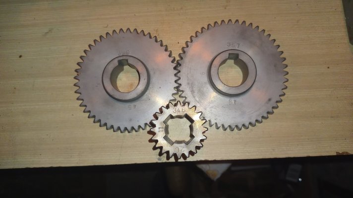
Nitride coating in theory doesn't change the dimensions of the part, which means it can be machined to final dimensions.
In my case, all de dimensions changed significally, around 0,3mm/200mm distorsion can be measured. The parts got bigger in all dimensions, rhe hole size shrinked..
The calculated tooth gap mostly disappeared, only 0,02mm remained, that means, that this is the maximal tolerance for the gear-pair's geometry, and that's not much in this case.
The final result will be revealed on Sunday, I will try to assemble the transmission. Hope for the best, wish me luck.


