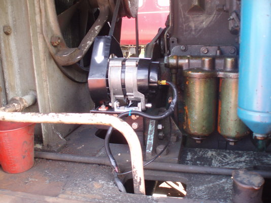
The dynamo has 3 wires attached to it, a fat red one and 2 less fat black ones, should one of the wires become energised with the ignition on? I've a feeling that the dynamo is ok cos every thing looks so new inside it,I need as much ammo as possible before I send it to the guys that indulge in that type of black art.
My understanding is... There should be a live (ignition) feed to the regulator but not to the dynamo. When the dynamo spins up, the residual magnetism in the field coils generate enough power to close the contacts in the regulator which connects the battery to the field coils and away you go. If the dynamo has been left for ages it will have no residual and it won't energise the regulator. See 'flashing the field' above. The large red lead is probably the output and one or both of the black ones will be the field windings; you'd expect one to be earthed but maybe they both go back to the regulator?
Hi, yes you're right, one of the blacks is for the field, the other black and the red are from the battery via the regulator. Commercial dynamos like this are not earth return but wired separately. Colin
Well, I refitted the dynamo and flashed the F terminal (several times) and nothing, the amp meter shows discharge on starting but nothing on running, also the IGN warning light doesn't come on at all, the bulb is OK. Had about 5 Hours play with it yesterday so it's going to get a proper dark artist to have ago at it. Norm
Never worked on a dynamo...but the physics behind it is "fairly" simple. Basically a copper conductor moving through a magnetic field generates a current...if you have the coils powered up then the magnetic field should be strong enough to deflect a compass. If the fields is detected then you can assume the problem is with the conductor coils...would be interesting to see pics of what they look like inside (but only if you have it apart).
I've went as far as my limited knowledge and patience of electrickery will take me and await the dark artist and I will report his findings.
Latest. I need a couple of headlights for the loco, looked at a few places on the net but find the nearest seem to be old Land rover, could probably fit them but the original would mean no faffing, there're Lucas 7 inch old sealed beam type, as the pics show a little bit of pitting here and there. And the guy from the dark arts is coming to sort the charging problem tomorrow.
The guy from the dark arts (electrickery) came today, first word, Kinell, Gave it a good coat of looking at (nearly 2 hours) the fault seams to be from the ign switch to where ever it feeds but couldn't trace it, he said we really need a wiring diagram for it, easier said than done. had the dash out and most of the wiring is coloured yellow and all soldered to inst and switches, also the wiring being in conduit kind of hampers things.
If by dynamo you mean charge alternator, most of the bigger ones require an excitation feed, this would normally be called the field winding, usually a 12 or 24vdc supply via a 200ohm resistor, on power alternators you can have field winding auxiliary excitation, which creates excitation current via and aux winding but can loose residual magnetism and some times needs to be flashed with battery voltage, if you maintain the voltage you will get a fixed output voltage, if it a permanent magnet excitation the it sold work every time. a surge in current at the start an then loss would indicate that the alternator isn't getting excitation current. you will also have freewheeling diodes in there as well which need to be checked.
It's a 60 year dynamo that's done 250 Hrs work. it's been flashed etc the difficulty seems to be tracing the wiring.
All soldered behind the dash etc. Done my bit now I got it running etc the electrickery is down to some one else now. I think Staffwold barn railway have the wiring diagrams I've contacted them twice, same answer, fone back next week. I've just found out that they tried to buy/lease the loco and the place it's at told them it's not for sale or lease. I think there's some professional jealously going on, anyway next thing is the air brake system.
Sounds like big boys model railway clubs if I did ever know them... had some very weird experiences with places that ask for volunteers yet actually just want to do it all themselves and cry ‘struggling’. At least you’re getting paid!
Been off the net for a while ( not paying twice for it) so on it where and when. Sorted the charging system out, Left the old dynamo in situ and fitted an alternator at the front. On with the brakes now as everything is seized solid.
What was the thinking there? Was it to preserve originality or is the dynamo fulfilling another function?
The dynamo is gear driven and fits in to the rear of the block, so rather than make a blanking plate it's been left in situ.
Hi, The engine looks like it's driving a compressor in the foreground of pic 2 (seen better in the pics in post 67) and possibly a jack shaft below out of sight, a belt from that is driving the alternator and the cooling fan for the main radiator. Perhaps mechman can confirm or deny. Colin Edit: A pic in post 39 shows the original set up.
The original belt was only driving the rad cooling fan, so that seemed the best place to try and fit an alternator, took a while but got there , brackets lining up etc . I used a link belt to get the belt size required and took it from there. ( £ 28 with discount)