God mode restorations
Member
- Messages
- 8,100
- Location
- uk colchester
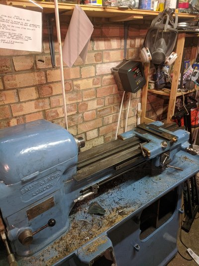
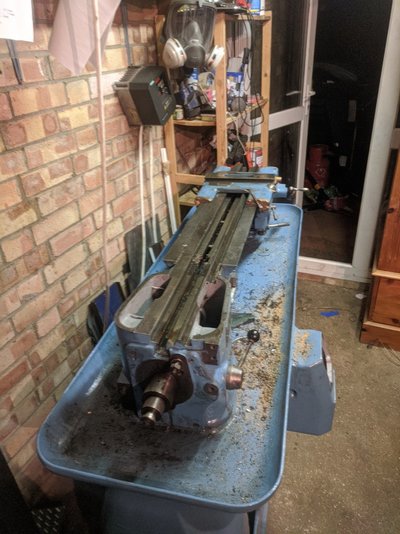
Yer it's a bit dearNot the only one who likes blue on an S&B dont like the price mind even for a mk2
https://www.ebay.co.uk/itm/SMART-AN...599882?hash=item261a83c28a:g:jz8AAOSwCcBctvYL