


You are using an out of date browser. It may not display this or other websites correctly.
You should upgrade or use an alternative browser.
You should upgrade or use an alternative browser.
clarke 100e wire feed problem
- Thread starter mini mad
- Start date
have recently recieved the transformer and fitted it however i got the 1x18 and it still had 6 pins but only 4 of which worked removed the ones which were not needed which allowed me to install the transformer on the curcuit board its self so didnt have to mess around with mounting else where and runing wires to it only cost £4:50 or so will give the part number if anyone would like it
oh yes the welder now works like new thanks to all that helped me out")
oh yes the welder now works like new thanks to all that helped me out
And
Yes exactly.. Post the part number as people like me have the same problem and need that exact part.
Or you could just fix your own and then run, without any further threads or help for anyone else, int that right Kieth..
What a plonker.. Whats this part exactly mentioned above and could someone post a link to a replacement transformer for a dodgy wire feed which ive linked back to the PCB. Its a Clarke 100EN Turbo
mike 109444
Member
- Messages
- 4,878
Sapwood you could try a polite PM to Mini Mad asking him for the number and reminding him of posting the part number on here : )
Oh and welcome to the forum
Oh and welcome to the forum
Hmm, a pity he didn't post more details once it was sorted. Good manners and all that...
This should do the job, a fairly cheap encapsulated version:
http://uk.farnell.com/myrra/44197/transformer-3-2va-18v/dp/1689077
So long as it will fit on the board.
And this one, a heavier duty job which Scott posted, with a bit more in reserve:
http://uk.farnell.com/pro-power/ctfcs6-18/transformer-6va-2-x-18v/dp/1780872
If this one is too big to fit on the pcb it could be chassis mounted on a plate nearby, as Scott suggested.
Hmm, a pity he didn't post more details once it was sorted. Good manners and all that...
This should do the job, a fairly cheap encapsulated version:
http://uk.farnell.com/myrra/44197/transformer-3-2va-18v/dp/1689077
So long as it will fit on the board.
And this one, a heavier duty job which Scott posted, with a bit more in reserve:
http://uk.farnell.com/pro-power/ctfcs6-18/transformer-6va-2-x-18v/dp/1780872
If this one is too big to fit on the pcb it could be chassis mounted on a plate nearby, as Scott suggested.
I will tell you a little about what ive done so far to check this problem 100en turbo
Wire feed problem, no wire motor power.
Connected 12v on motor and its fine.
Checked continuity on trigger/gun and the circuit their is fine, no broken connection from trigger to welder.
So this pointed me finaly to the PCB. I checked resistance on the potentiometer and it goes up fine from 0-7 then it drops down to near enough zero, despite going higher. Would this be a problematic pot?
Im thinking I would sooner replace individual parts on this PCB rather than pay £40 for a whole new one.
Though looking at the schematics of the back of the board, it looks to me like the pot affects pretty much every aspect of the board.
I obviously just need to identify the wire feed part of this pcb and replace the faulty components with that part.
Or??? Am I wrong..? Do you know what vital components I could change to repair this board to get the wire feed running again, or is their no point, is it a whole new board?
Or? Am I barking up the wrong tree altogether? Is it something else ive missed and not mentioned here and checked myself?
Can you help? I could mail you a pic of the pcb if it helps you figure it out better?
sapwood@hotmail.co.uk or call 0191 5815340
Im sure theirs a drink in this for you mate.
Shenion messaged me saying that he thinks the relay and transformer are fine, telling me to check Diodes and transistors..
If I post a picture of this board can some of you guys help with this?
Its a very very similar board to the one pictured on this thread, which is why I came here, its identical in parts, if only mine is a newer model 100en turbo???
Heres the boarb pics if anyone could circle whats what, diodes, transistors, transformer etc etc. Im not the best at this, for a sound engineer you'd think my electronics would be upto scrathc. But hey ho, my equipment usualy works, so all I ever have to do is PLAY!
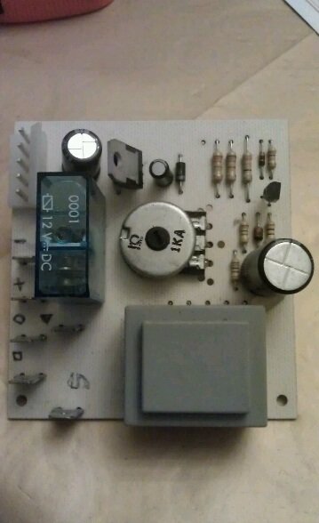

Heres the boarb pics if anyone could circle whats what, diodes, transistors, transformer etc etc. Im not the best at this, for a sound engineer you'd think my electronics would be upto scrathc. But hey ho, my equipment usualy works, so all I ever have to do is PLAY!
The £40 from clarke for a whole new board is seeming ever more tempting... Grunt Grunt!
Have you checked out the transformer windings already?
Diodes and particularly transistors generally have to be disconnected from the board to be tested properly.
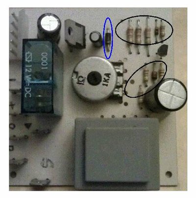
They are generally cheap enough to replace. The transistors are the stripey ones in the black rings. The striped bands represent values, as you probably know, so if you find a duff one you must replace with one of the same coding value. If you are testing them you need to know the values, in case any are in the process of breaking down. If they are open - no reading at any setting - then they need replacing.
There is probably only one diode in there, as marked in the blue ring. That should take current one way only. If it does anything else, like both ways or nothing, it's shot.
The big flat job in the bottom of the pic is the transformer that had to be replaced in mini mad's m/c, I think. You say you have already checked the relay, too? The box on your left as you look at the pic.
The big fat cylinders with shiny tops are caps, they sometimes blow, but it's usually obvious.
Like you, I haven't got into this circuit stuff in a long while, but when its necessary you gotta try to recall all this stuff...
Diodes and particularly transistors generally have to be disconnected from the board to be tested properly.
They are generally cheap enough to replace. The transistors are the stripey ones in the black rings. The striped bands represent values, as you probably know, so if you find a duff one you must replace with one of the same coding value. If you are testing them you need to know the values, in case any are in the process of breaking down. If they are open - no reading at any setting - then they need replacing.
There is probably only one diode in there, as marked in the blue ring. That should take current one way only. If it does anything else, like both ways or nothing, it's shot.
The big flat job in the bottom of the pic is the transformer that had to be replaced in mini mad's m/c, I think. You say you have already checked the relay, too? The box on your left as you look at the pic.
The big fat cylinders with shiny tops are caps, they sometimes blow, but it's usually obvious.
Like you, I haven't got into this circuit stuff in a long while, but when its necessary you gotta try to recall all this stuff...
I will check those transistors and the diode as you said and see what I come up with from this.
I hadnt done anything to check the relay, unless checking for an arc was doing so?
What about the transformer? If all these transistors and the diode check out alright, then where would you point your finger?
Can I check the transformer and relay in anyway?
I hadnt done anything to check the relay, unless checking for an arc was doing so?
What about the transformer? If all these transistors and the diode check out alright, then where would you point your finger?
Can I check the transformer and relay in anyway?
Have you checked out the transformer windings already?
Diodes and particularly transistors generally have to be disconnected from the board to be tested properly.
They are generally cheap enough to replace. The transistors are the stripey ones in the black rings. The striped bands represent values, as you probably know, so if you find a duff one you must replace with one of the same coding value. If you are testing them you need to know the values, in case any are in the process of breaking down. If they are open - no reading at any setting - then they need replacing.
There is probably only one diode in there, as marked in the blue ring. That should take current one way only. If it does anything else, like both ways or nothing, it's shot.
The big flat job in the bottom of the pic is the transformer that had to be replaced in mini mad's m/c, I think. You say you have already checked the relay, too? The box on your left as you look at the pic.
The big fat cylinders with shiny tops are caps, they sometimes blow, but it's usually obvious.
Like you, I haven't got into this circuit stuff in a long while, but when its necessary you gotta try to recall all this stuff...
Got something at least here.
See the transistors in the lower black circle you did for me? The one on the far right of pic isnt doing anything at all, not giving any reading, as if its SHOT. Im getting readings from all others. Im testing them on the bnoard, which my dad says ISNT an accurate reading, but at least its telling me which are doing something - RIGHT??? Whereas the far right transistor in the lower black circle isnt PLAYING at all...
What you think???
You could try removing that one resistor and testing it on its own, but check what value it is first. Some have a high resistance. Most of those components ringed in black are actually only resistors, but will still stop the m/c working properly if they pack up. Cheap to replace, but job has to be done carefully, without overheating other components nearby.
You could try removing that one resistor and testing it on its own, but check what value it is first. Some have a high resistance. Most of those components ringed in black are actually only resistors, but will still stop the m/c working properly if they pack up. Cheap to replace, but job has to be done carefully, without overheating other components nearby.
But would you be getting the same feeling as I am if you were testing this and you couldnt find ANY reading from that one resistor? All the others gave me a reading, this one wouldnt, and following the circuit, one side of it goes straight to a pin for an out cable and the other goes to the small black semi circle shaped 'Thingy' directly above it in picture.
From the bottom pin of the pot in picture the circuit runs from this to a resistor, then to the problem resistor and thereafter directly to a pin/connector where wiring goes out to wherever. Its the pin in the centre of the five pin block connector at top left of board picture.
Based on what ive told you would you be fairly confident this is a shot resistor, or can their be a reason for no reading from a resistor like im getting, even though one doing this may be fine?
I cant thankyou enough for your help Kieth mate..
If you ever want anything making for your home, I run a cabinet making one man band business, making bespoke pieces form gorgeous hardwoods.
Ebay - Bespokesapwooddesigns ~Their will be cost only on all items I make if you evr need anything for helping me Kieth. Thanks so much mate.
Hi Sapwood,
The main reason it is best to test most electronics component off the board, is that the test current can run backwards through the circuit sometimes, and make its way to the other side of a device without actually going through it. What it encounters on its way will affect the readings on the voltmeter.
But if you are getting no readings at all it suggests the resistor has failed and is open circuit, that is, letting no current through at all. Because if there was a path to the other side of the resistor you would have got a reading, and if there was no path, you should still have got some kind of a reading through the resistor. Before you remove it, note which way the coloured rings on it are facing, and put the new one back the same way.
When removing it, use a fairly small soldering iron, get this hot first, then apply it to only one soldered connection of the resistor, under the board, and gently ease the wire out of the top of the board as the solder melts. Make the operation as quick as possible to avoid overheating anything else on the board. A small sharp-nosed pliars is useful.
Try to have the board supported firmly while you are doing this, it makes this sort of work much easier. On its end is best so you can work both sides.
When you have one end out, get the soldering iron hot again before you take the remaining wire out.
It is much better to use a hot iron very quickly than use a warm iron kept held against the solder hoping it will melt. All that is happening with a warm iron is that the heat is going into heating the board, sometimes with dire consequences.
Apologies if you know all this, but it is better to be safe than sorry.
Test your resistor once it's out, and replace it with a new one if it is dead.
Make sure you get one the exact same value. Test it and note its reading.
While you are waiting on the resistor, try testing anything else on the board.
When replacing the resistor, much the same applies. Heat the back of the hole with a hot iron if it's filled with solder, and blow through from the top to clear the solder out. (If you have a solder wick or suction tool use that, but we don't all have them).
Do whichever end is the most awkward first. Once the wires are soldered in, recheck your resistor. You may get a different reading if there is a return path.
Best check out the rest of the board while its out, so far as possible.
Many thanks for the cabinet offer, it is very much appreciated.
But doing this is helping me as much as you, because like many more on here I have a Clarke, and this could happen to me tomorrow, so the sooner we can all figure inexpensive ways of fixing things the better.
Will give this a go in a couple of days.
Had a nightmare day today. Everything gone wrong to be honest.
Im behind on orders, which I hate.
My compressor that I just bought is running fine, though new hose, fittings and a few second hand tools arent grafting, problem with line setup someplace.
Plus the jonsered xf chainsaw I just bought secondhand isnt reving as it should do, got very little power at all at full throttle to be honest, need to service the carb on that.
Probably best I didnt touch the Welder today going off everything else EH!


