Congratulations on being able to install this modification successfully!
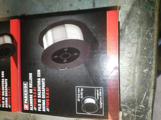
With this "dimmer" you have been able to solve the problem of coarse 2- or 4- step switched power ranges, and provide a low-end MIG welder with fully variable welding power control starting at a low level, making it suitable for use on thin metal.
It would be helpful to others who want to try this if you could provide a link to the actual Amazon-supplied device that you have fitted?
As the next step, adding an inductor in the return cable after the capacitors is highly recommended. It will provide a smoother arc with less spatter, and will also reduce the surge loading on the rectifier and the capacitors.
On your machine, power for the wirefeed motor and the speed control circuit is supplied by the main welding transformer, so if you use the "dimmer" to reduce power in that transformer, it will also affect the wire speed. To solve this, you would need to add a separate stabilised 12v or 24v motor power supply.
To allow discharge of the added capacitors and prevent the annoying "live torch" effect, you need to add a bleeder resistor across the capacitors. This would typically be a 30 or 50 Ohm, 20 Watt wirewound resistor. Machines that use a Contactor ( heavy-duty relay ) to power-on the main welding transformer often have an additional pair of normally-closed contacts which put the bleeder resistor across the capacitors when the transformer is not energised. In your case, I think there is just a medium-sized relay on the PCB with only one pair of normally-open contacts. In this situation, the bleeder resistor can be wired permanently across the capacitors, but it will waste a bit of power.
The additional wiring with thick flexible cables could be tidied up by using copper cable lugs, such as:

It would be interesting to measure the output voltage that can now be adjusted, from the torch tip to the work return clamp, as you turn up the power.
Put the dimmer knob at minimum, set the welder power switches at "MAX" and "2", and let us know what voltage range is possible.
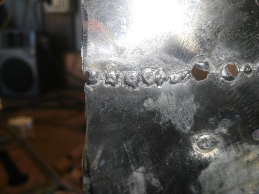
Additionally, as Memmeddu requests, whenever you can please post some photographs of the weld results.
With this "dimmer" you have been able to solve the problem of coarse 2- or 4- step switched power ranges, and provide a low-end MIG welder with fully variable welding power control starting at a low level, making it suitable for use on thin metal.
It would be helpful to others who want to try this if you could provide a link to the actual Amazon-supplied device that you have fitted?
As the next step, adding an inductor in the return cable after the capacitors is highly recommended. It will provide a smoother arc with less spatter, and will also reduce the surge loading on the rectifier and the capacitors.
On your machine, power for the wirefeed motor and the speed control circuit is supplied by the main welding transformer, so if you use the "dimmer" to reduce power in that transformer, it will also affect the wire speed. To solve this, you would need to add a separate stabilised 12v or 24v motor power supply.
To allow discharge of the added capacitors and prevent the annoying "live torch" effect, you need to add a bleeder resistor across the capacitors. This would typically be a 30 or 50 Ohm, 20 Watt wirewound resistor. Machines that use a Contactor ( heavy-duty relay ) to power-on the main welding transformer often have an additional pair of normally-closed contacts which put the bleeder resistor across the capacitors when the transformer is not energised. In your case, I think there is just a medium-sized relay on the PCB with only one pair of normally-open contacts. In this situation, the bleeder resistor can be wired permanently across the capacitors, but it will waste a bit of power.
The additional wiring with thick flexible cables could be tidied up by using copper cable lugs, such as:
It would be interesting to measure the output voltage that can now be adjusted, from the torch tip to the work return clamp, as you turn up the power.
Put the dimmer knob at minimum, set the welder power switches at "MAX" and "2", and let us know what voltage range is possible.
Additionally, as Memmeddu requests, whenever you can please post some photographs of the weld results.


 - but is the dimmer used in conjunction with the step switches, or does it take the place of them?