brewdexta
The biggest tool in the box
- Messages
- 5,825
- Location
- UK
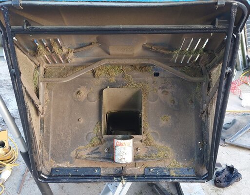
Well its only been 6 months, about time I got back to this one and try and diagnose the gutless motor that I converted from start to delta by diving into the windings. I thought I had inadvertently reversed an a1 with an a2 or similar with b or c.Started to fix the Tom Senior M1, or rather the motor and VFD. I converted the original Brooks Gryphon motor from star to delta by finding the star point and breaking it out into the individual windings. However, it was gutless. Life got in the way, and I acquired another Tom Senior, a light vertical, which meant I've only just got around to fixing it.
I suspect that I have one winding reversed, that is instead of a2 connecting to b1, and b2 to c1 and c2 to a1, one of these is reversed. I thought I would use the induced voltage method testing, using a 10v AC power supply, if its the right way around you get about 4v induced into the other winding. If all else fails I have a new motor, but that involves broaching a keyway.
I'm also replacing the VFD with a cold plate VFD, no annoying fan! I have a 40 ohm, 200 watt brake resistor on order, I'll compare before and after to see how much faster it slows down.
Pics next time, I'm in the pub!
When I took it apart, it was obvious which one are a1, b1, c1 as they had the original black wiring connected to the external connection block. a2, b2 and c2 were in newer brown wiring that I used to extend the star point to the connection block. Before breaking it out, the motor would have been wired like this with the a2, b2 and c2 connected together at the star point as per the diagram below.
Tapping out the connections with the ohmmeter proved this to be so, I also checked the resistance of each coil, all about 12 ohms. I chased out how I had wired it when last working and it does seem to be all correct and now in delta formation as per below.
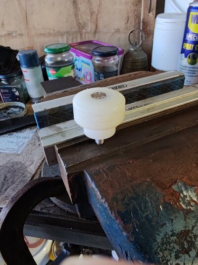
Just to be sure, I used the induced voltage method to double check, this is from another forum. I had bought an AC transformer for this forgetting that the wiring would be a different colour so thought I may as well check it out. The clips on the motor connection plate have the 9v AC supply.
"If you label the wires as A&A, B&B, C&C, then connect one of the B's to one of the C's
Connect the low voltage supply to the wires A&A
Then check for an induced voltage across the wires B & C that are not joined together. If a voltage is present the you have connected a B1 to a C2 - if not then you have connected a B1 to a C1. A voltage of 10VAC supplied to A&A will give about 4VAC across the B&C wires.
Then use this method again with the A&C wires joined and voltage applied to wires B1 & B2"
This confirmed I was doing it right, but the voltage was only about 2.8v instead of the 4v quoted above. I repeated this for all 3.
It looks like the motor is wired correctly. I'm tempted to try it with the new inverter before swapping it out for the new modern 2hp motor that I have as will need to broach a keyway, which means I will have to get back on the hydraulic press project.
So, not fixed yet but getting closer......