You are using an out of date browser. It may not display this or other websites correctly.
You should upgrade or use an alternative browser.
You should upgrade or use an alternative browser.
Rotary switch help please .
- Thread starter JBZX
- Start date
The wire for the jumpers should be a similar gauge to that used for the connections to the transformer. Ideally, the wire should be insulated where it is exposed. The jumpers in the original Kende cam switch were made from stamped sheet, and not insulated, so would expose live surfaces inside the welder. It will be a bit fiddly, making all of the connections but, hey. Hopefully it will be worth it.
Thanks,A similar gauge to that used for the connections to the transformer should do. Ideally, the wire should be insulated. The jumpers in the original Kende cam switch were made from stamped sheet, and not insulated, so would expose live surfaces inside the welder.
In post #34 could you explain what I need to do for that please? (does it mean, no need for separate switch?)
Thanks again.
Yes, the new switch has two on/off switches at every active position ( other than "0" ), so one of these two is used as the main switch, with no need for a separate power switch. The jumpering-together of switch terminals 4, 8, 12, and 16 and connecting them to Live provides this main switch.In post #34 could you explain what I need to do for that please? (does it mean, no need for separate switch?)
Thanks Eddie.Yes, the new switch has two on/off switches at every active position ( other than "0" ), so one of these two is used as the main switch, with no need for a separate power switch. The jumpering-together of switch terminals 4, 8, 12, and 16 and connecting them to Live provides this main switch.
Going to wire it up today will post pics once done.
So you guys can give my work the once over please.
Once again appreciate the knowledge and help of you all.
Hi All,
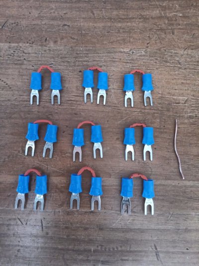
Made jumper wires photo 1.
Hope wire guage looks ok?
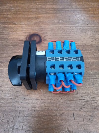
Photo 2, 3
Joined terminals 4,8,12,16 with jumper wires.
Joined terminals 2,6,10,14 with jumper wires.
Joined terminals 3,7,11,15 with jumper wires.
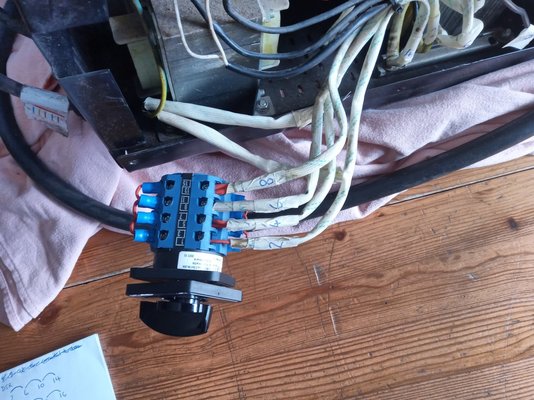
Photo 4
Transformer wire 2 to terminal 1
Transformer wire 4 to terminal 5
Transformer wire 6 to terminal 9
Transformer wire 8 to terminal 13.
Hope all above is correct.?
Could you tell me where to position remaining wires listed below please?
11 (blue wire)
7 (brown wire)
10 (white wire to fan, white wire to Power display light, black wire to 4th pcb spade)
12 (white wire to fan, white wire to Power display light, red wire to Thermal Overload display light, black wire to rear of transformer)
Look forward to completing this, hopefully successfully with all your brilliant help.
You can probably tell how nervous I am by the amount of info I'm trying to provide.
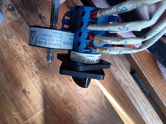
Also noticed the original "KENDE" switch was 690V 20A and new switch is 660V 20A ,photo 5, is this a problem?
Sorry for being an absolute pain to you all.


Live ( was Pin 7) Brown - any one of 4,8,12,16
Neutral (was pin 11) any one of 2,6,10,14
Wires (was pin 10) go to joined terminals 3,7,11,15.
Wires (was ping 12) go to either pin 13 OR joined pins 2,6,10,14.
I'd try Pin 12 to pin 13 first and see if it works OK on all ranges, if it does, then leave it there. If the relay won't click in on the lowest setting, move what was pin 12 to any of 2,6,10,14.
See post #39 (this is for future readers - post #39 says "10,6,10,14" - it should be be 2,6,10,14)
D
Neutral (was pin 11) any one of 2,6,10,14
Wires (was pin 10) go to joined terminals 3,7,11,15.
Wires (was ping 12) go to either pin 13 OR joined pins 2,6,10,14.
I'd try Pin 12 to pin 13 first and see if it works OK on all ranges, if it does, then leave it there. If the relay won't click in on the lowest setting, move what was pin 12 to any of 2,6,10,14.
See post #39
 (this is for future readers - post #39 says "10,6,10,14" - it should be be 2,6,10,14)
D
Wedg1e
They call me Mr. Bodge-angles
- Messages
- 7,893
- Location
- Teesside, England
Technical Arc Services in York do (or used to) sell a few rotary switches... but they do like to charge 
Those blue Kraus and Naimer switches can take some thinking about; luckily on a MIG set you normally only need a single-pole switching action. Try a 4-pole 5-way version and see if you have any hair left
I use them for x-ray bay interlock selectors, always end up making my own truth table before connecting anything, just in case.

Those blue Kraus and Naimer switches can take some thinking about; luckily on a MIG set you normally only need a single-pole switching action. Try a 4-pole 5-way version and see if you have any hair left

I use them for x-ray bay interlock selectors, always end up making my own truth table before connecting anything, just in case.
Live ( was Pin 7) Brown - any one of 4,8,12,16
Neutral (was pin 11) any one of 2,6,10,14
Wires (was pin 10) go to joined terminals 3,7,11,15.
Wires (was ping 12) go to either pin 13 OR joined pins 2,6,10,14.
I'd try Pin 12 to pin 13 first and see if it works OK on all ranges, if it does, then leave it there. If the relay won't click in on the lowest setting, move what was pin 12 to any of 2,6,10,14.
See post #39(this is for future readers - post #39 says "10,6,10,14" - it should be be 2,6,10,14)
D
Cheers DSR,Live ( was Pin 7) Brown - any one of 4,8,12,16
Neutral (was pin 11) any one of 2,6,10,14
Wires (was pin 10) go to joined terminals 3,7,11,15.
Wires (was ping 12) go to either pin 13 OR joined pins 2,6,10,14.
I'd try Pin 12 to pin 13 first and see if it works OK on all ranges, if it does, then leave it there. If the relay won't click in on the lowest setting, move what was pin 12 to any of 2,6,10,14.
See post #39(this is for future readers - post #39 says "10,6,10,14" - it should be be 2,6,10,14)
D
Can't thank you enough, you're a star. Is the 660V 20A instead of 690V 20A any issue?
Will couple up in morning and keep you posted.
Can't thank you enough, you're a star. Is the 660V 20A instead of 690V 20A any issue?
I wouldn't worry about it, it's well above the supply voltage (240ish volts) in GB, and the current is the same and that's more important, breaking higher currents wears the contacts quicker but that will only happen if you are turning the welder on and off by this switch a lot while you are actually welding
 Max primary current is well within the limits of the switch and the wear will really be in the 30A relay as that's what switches the transformer on and off when you press/release the torch trigger.
D
Thanks.I wouldn't worry about it, it's well above the supply voltage (240ish volts) in GB, and the current is the same and that's more important, breaking higher currents wears the contacts quicker but that will only happen if you are turning the welder on and off by this switch a lot while you are actually weldingMax primary current is well within the limits of the switch and the wear will really be in the 30A relay as that's what switches the transformer on and off when you press/release the torch trigger.
D
Will be in touch with update tomorrow.
As you know, I haven't got a clue about all this so prefer to listen to people who know their stuff, like yourself.
If anyone else experiences the same as what I have would the switch in attached photos be of use to them?
Might be no good but just thought I'd mention.
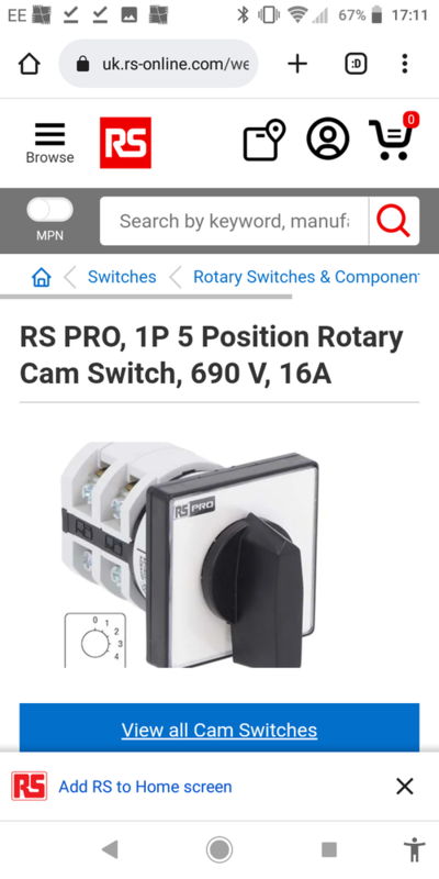
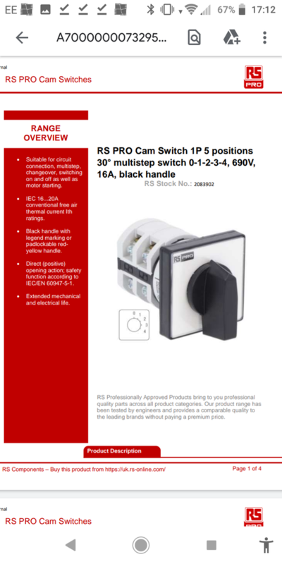
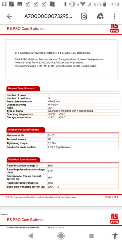

 Oh well, sorry guys, I gave it my best shot but obviously, I'm not up to the job.
Firstly tried wire 12 to terminal 13 and 1st position Power light on + fan, I thought
 for a couple of seconds then pressed trigger and
  just clicking from relay but nothing else on any of 4 settings.
So transferred wire 12 to terminal 14 (2,6,10,14) and just the same as using terminal 13.

Sorry I haven't been able to have success, really appreciate the help and input of everyone who messaged in the thread

Don't give up yet - when you say just clicking from relay, which relay is this?Oh well, sorry guys, I gave it my best shot but obviously, I'm not up to the job.
Firstly tried wire 12 to terminal 13 and 1st position Power light on + fan, I thoughtfor a couple of seconds then pressed trigger and
just clicking from relay but nothing else on any of 4 settings.
So transferred wire 12 to terminal 14 (2,6,10,14) and just the same as using terminal 13.
Sorry I haven't been able to have success, really appreciate the help and input of everyone who messaged in the thread
Too true mate.at least your still alive to tell the tale
where theres life theres hope ....
gods another of my grandads old sayings ,,,,

Thanks, its the relay on pcb.Don't give up yet - when you say just clicking from relay, which relay is this?


