


You are using an out of date browser. It may not display this or other websites correctly.
You should upgrade or use an alternative browser.
You should upgrade or use an alternative browser.
help with repair of my euromig 260 mig welder
- Thread starter jorva
- Start date
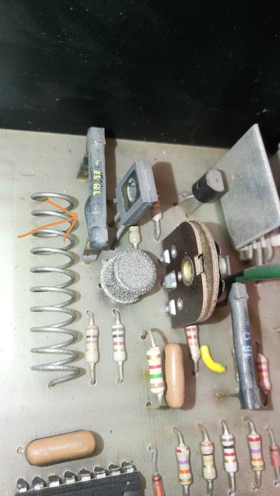
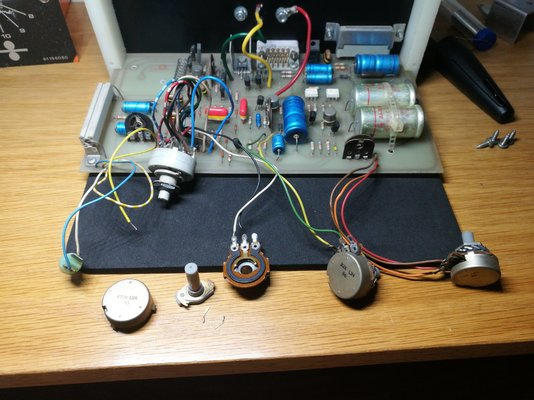
That's a wirewound resistor.
I'd check the two transistors near it too.
Seems like the the black one has gone pop it has a crack and is thicker where the crack is.
Mhh ich ones do you mean? The big ones where doable for me but if I have to start with the small things I am afraid that I Wil ruin the pcb.
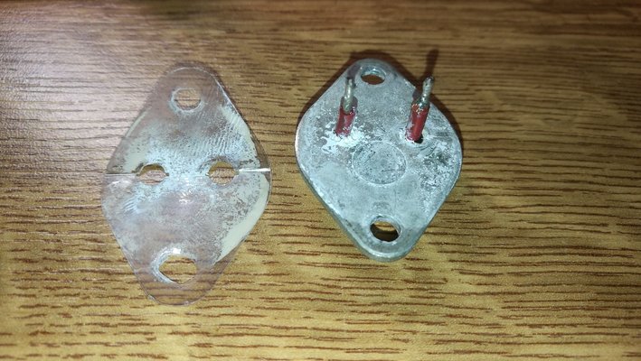
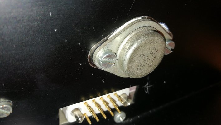
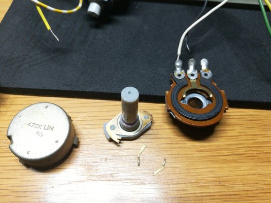
The heat sink compound, or thermal paste, is there to provide good conduction of heat from the semiconductor to the heatsink. A component that has a "live" case may need to be electrically insulated from the heatsink - such as by the mica washer that you have shown. There will also be insulating shouldered nylon washers on the mounting screws. The electrical connection to the case of the 2N3055 transistor will be taken care of by a solder tag with a wire.
Seadog
Save the planet. It's the only one with rum!
- Messages
- 13,231
- Location
- NE London - UK
Mhh ich ones do you mean?
The crusty silver can beneath it, in the picture, and the flat black one to the right of it.
The bridge rectifier that I mentioned, to convert 24v AC from the small transformer to 24v DC to run the wirefeed motor etc., is probably the rectangular grey plastic component clipped to the heatsink.
The black wirewound resistor will have a low resistance ( there is one near it labelled 18 ohms ). You can check if it has been broken open-circuit, due to the crack, using your meter on the resistance range. If it is still OK, this low resistance will be shown regardless of other components still in the circuit.
The black wirewound resistor will have a low resistance ( there is one near it labelled 18 ohms ). You can check if it has been broken open-circuit, due to the crack, using your meter on the resistance range. If it is still OK, this low resistance will be shown regardless of other components still in the circuit.
The bridge rectifier that I mentioned, to convert 24v AC from the small transformer to 24v DC to run the wirefeed motor etc., is probably the rectangular grey plastic component clipped to the heatsink.
The black wirewound resistor will have a low resistance ( there is one near it labelled 18 ohms ). You can check if it has been broken open-circuit, due to the crack, using your meter on the resistance range. If it is still OK, this low resistance will be shown regardless of other components still in the circuit.
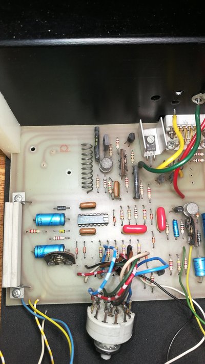
You mean the one the right upper corner?
It has 4 legs and it goes to the connectors for that has the 24v coming from the transformer and also one ire that goes to the gas solenoid
I have measured both wire wound resistors and both measure .041
To answer your previous question about the wire feed, as far as I can remember we here able to control te wire speed but is woud just keep running.
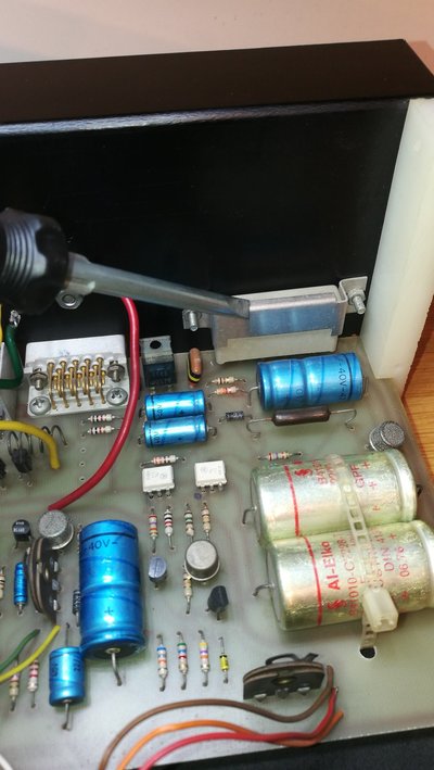
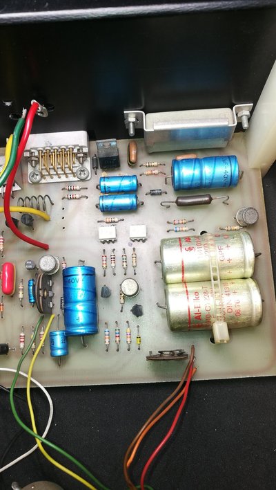
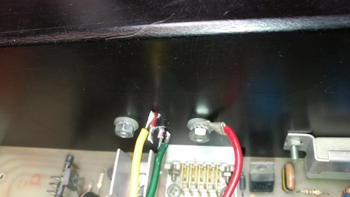
Yes, that's the rectifier. It has 4 legs - two for AC in, and two ( + and - ) for DC out. The motor and the gas solenoid will be 24v, maybe the Contactor coil too. There is probably a voltage regulator to drop to a lower voltage, maybe 15v, for the rest of the logic on this board. The DC will be smoothed by the two fat yellow capacitors.
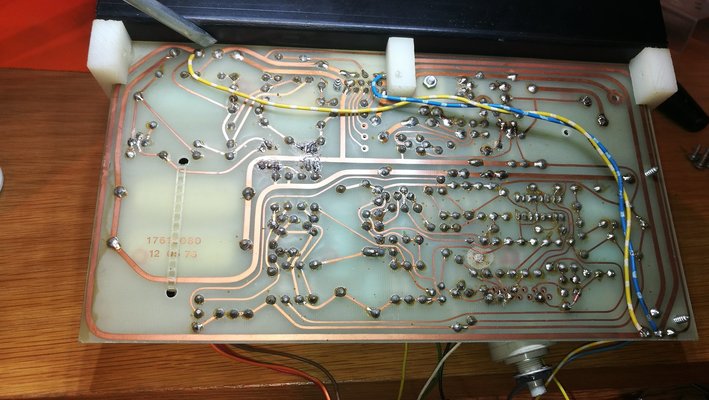
The yellow wire, and maybe the blue one too, were perhaps added by the workshop that tried to repair the board. Maybe they thought that the PCB tracks were damaged, or they cut tracks during the troubleshooting process and then bridged them with these long wires. Cutting tracks is OK, but after testing the usual method would be to just solder a short piece of bare solid wire across the cuts.
The yellow wire, and maybe the blue one too, were perhaps added by the workshop that tried to repair the board. Maybe they thought that the PCB tracks were damaged, or they cut tracks during the troubleshooting process and then bridged them with these long wires. Cutting tracks is OK, but after testing the usual method would be to just solder a short piece of bare solid wire across the cuts.
I was just playing around with the multimeter measuring the potentiometers and 2 out of 3 work like they shoud but then nr3 did nothing just in one spot the multimeter woud jump an go back to 0. So I opend the potmeter and saw the legs where not touching the ring I just touched them with the measuring pin of the multimeter and both pins fell of... Oops
It is the potentiometer next to the selector switch for spot welding ect I gues this one is for the delay when stitch welding or how long it spot welds.
Going to get myself a new potentiometer tomorow seems like the local dealer has them in stock.
It is the potentiometer next to the selector switch for spot welding ect I gues this one is for the delay when stitch welding or how long it spot welds.
Going to get myself a new potentiometer tomorow seems like the local dealer has them in stock.
Last edited:
It is bad luck that the 2N3055 which controls the wirefeed motor was not shorted. That would have been an easy and logical solution....
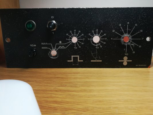
Regarding what I would call the "Mode" switch:
- normal welding - squeeze the torch trigger, welding power, gas, and wire fed on, release the trigger, all off
- spot welding - squeeze and hold the trigger, welder turns on, stays on for time determined by 2nd pot, then goes off
- stitch welding, squeeze and hold the trigger, move the torch, welder automatically turns on and off giving short welding stitches of length determined by 1st pot
However, that switch has FOUR positions ? The first position shows a continuous line, could this mean "feed the welding wire continuously, to help installing a new reel of wire" ? Does altering the setting of this switch have any effect on the "fault" ?
It is bad luck that the 2N3055 which controls the wirefeed motor was not shorted. That would have been an easy and logical solution....
Regarding what I would call the "Mode" switch:
- normal welding - squeeze the torch trigger, welding power, gas, and wire fed on, release the trigger, all off
- spot welding - squeeze and hold the trigger, welder turns on, stays on for time determined by 2nd pot, then goes off
- stitch welding, squeeze and hold the trigger, move the torch, welder automatically turns on and off giving short welding stitches of length determined by 1st pot
However, that switch has FOUR positions ? The first position shows a continuous line, could this mean "feed the welding wire continuously, to help installing a new reel of wire" ? Does altering the setting of this switch have any effect on the "fault" ?
Hello eddie, i am going to get 3 new pot meters in the afternoon ans also get the 4 position switch. the local electronics dealer has al of them in stock. And they are not expensive at al.
The 4 position switch was also bit hard to turn not like you woud expect from such a switch thats why i am also going to swap it out.
To be honest i have not tried the welder in a long time i just know it has this fault that the wire kept running and i did not try it before i took the pcb out now. i am going to swap out the pots and the switch an reistal the old transistors ( or shoud i put in the new ones?) and then i wil try the pcb on the welder and see what it does.
Seadog
Save the planet. It's the only one with rum!
- Messages
- 13,231
- Location
- NE London - UK
or shoud i put in the new ones?
One thing at a time or you'll never work out what the fault was.
So I replaced the switch and the 3 potentiometers. Put the old transistors back on their spot and then I tried it on the welder wire feed still runs and I can control the speed perfectly. Then I attached the torch and tried if tit woud weld/pull the contactor and it does not. I Wil post a video later
So i had no luck with replacing the switch and the potentiometers. (Woud have been to easy i gues) The switch i installed now is much better to turn the old one was very hard to turn in needed to put pliers on the pin to turn it when the knob was of. So at least that is an improvement...


