


You are using an out of date browser. It may not display this or other websites correctly.
You should upgrade or use an alternative browser.
You should upgrade or use an alternative browser.
FIMER X 1600 Resistor help?
- Thread starter Tonyg64
- Start date
 . I'll send this and try to find how to post a pic of said resistor.
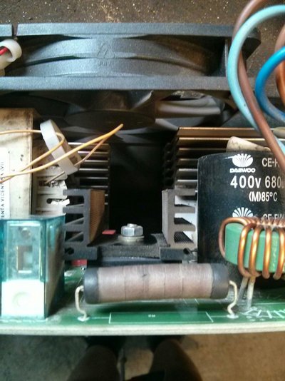
Tonyg64
Member
- Messages
- 42
- Location
- UK Warks
The brownish colour is actually the wire wrapped around a ceramic core. I soldered in a 5W 50 ohm ceramic I had here and it blew straight away so just random guesses on what to use really. The power led has not been lit since the resistor blew. Any help guys?
Cheers
Tony
Cheers
Tony
hobby_machinist
Member
- Messages
- 55
- Location
- Croatia
Im not an expert but all i can say is dont try to figure out the values of electric components by experimeting, also try to find out why that resistor failed becuase sometimes there is fault in other components that kill the other. Dont ask me how i learned that
Tonyg64
Member
- Messages
- 42
- Location
- UK Warks
Yes I realise its a shot in the dark at this stage but if I can find a resistor that works by choosing one that doesnt blow straight away I can then see what effects it has when welding. For reference I have a cheap clarke mig of my own and I looked in there and there is 2 4.7 ohm in parallel that are 7w each (but with different capacitor).
Cheers
Tony
Cheers
Tony

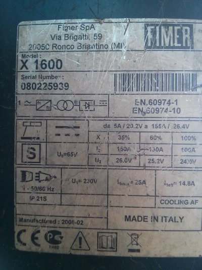
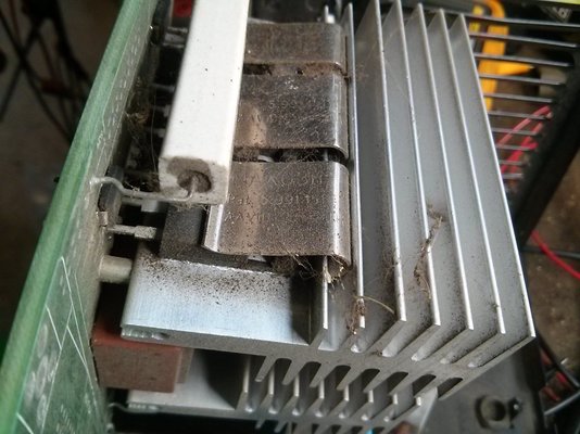
The Fimer X 1600 is an inverter arc welder. The AC mains input is rectified to 325v DC and smoothed by large electrolytic capacitors. In your picture, the rectifier may be the flat rectangular component with a black finned heatsink, behind the burnt resistor. A 680uF 400v capacitor is visible to the right.
The 325v DC bus runs the machine. It gets chopped to high-frequency AC by power transistors - MOSFETs or IGBTs, and then transformed and rectified again to provide the DC welding current output.
When the machine is first powered up, a soft-start circuit may be used to reduce the initial power surge whilst the capacitors charge. This can be a series resistor, which gets bypassed by a relay after a short power-on delay. The relay and the damaged resistor in your friend's machine may be part of that function.
Without a circuit diagram, you would have to trace the power cable connections and printed circuit board ( PCB ) tracks around the components I have mentioned above to confirm if this is true in your case. The soft-start resistor may be about 20 Ohms, and could be before or after the bridge rectifier. A short-circuit in the rectifier would cause the resistor to burn out. One or more shorted electrolytic capacitors would also have this effect. These components could be checked statically with a meter. They may have to be taken out of the circuit ( removed from the PCB ) to get valid results. If one or more of the switching power transistors is permanently on, or is shorted, that could also cause the pre-charge resistor to burn.
After investigating the circuit layout as suggested above, you could measure the AC mains coming in, the voltage across the burnt resistor, and the DC output of the rectifier. Check if the relay does close a few seconds after power-up. If the resistor is before the rectifier, you could replace the burnt resistor with a 100Watt mains incandescent light bulb ( effectively a 50-odd Ohm 100W resistor ) to get an idea of what is happening. In correct operation, the bulb should flash and go out. If is comes on at full brilliance or stays on, there is a short after it.
** Please be aware that dangerous high voltages are present in inverter welders. DC is more dangerous than AC. Voltages may be present across charged capacitors even after the machine has been powered off and disconnected from the AC mains. Do not work on this machine in a live condition unless you are confident and have the correct equipment.**
Tonyg64
Member
- Messages
- 42
- Location
- UK Warks
Eddie, firstly thanks for the brilliant reply mate. The circuit appears to me me to go from the switch to the capacitors, then to the burnt resistor , then the rectifier (with the heat sink as you said). With the rectifier still in circuit, I got measurements in all directions as if it was shorted on all diodes. I removed the rectifier and tested on the bench and it looks normal (one way flow only through diodes).The bulb idea I like so that may give more info. I ordered some 4.7 ohm / 7W resistors to try (which may be too small by your comments?). As a side note the burnt resistor as shown in the pic broke up when removing and the wire was detached at one point so on the bench I crudely twisted the wires together and strung it out and it measured 45 ohms, but whether or not that would be an accurate reading I couldnt be sure.
Cheers
Tony
Cheers
Tony

Tony, thank you for the extra pictures.
As hobby_machinist said, the resistor will be failing not because it is the wrong value, but because there is a fault in some other component.
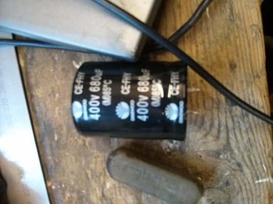
The capacitors are a prime candidate, but often they show it by bulging or exploding! Electrolytic capacitors will only work on DC, so the rectifier would have to come before the capacitors in the circuit. The two 680uF 400v caps will be in parallel, giving 1360uF.
Unless it has a dedicated capacitance range, a digital meter is not much use in checking a capacitor, but it may show you if there is a direct short circuit. An old-fashioned analogue meter, on the Ohms range, will show that the capacitor can charge, by the meter needle initially swinging over to the right, indicating low resistance, and then falling back to high resistance after the cap has fully charged using the voltage from the meter.
I would agree that 4.7 Ohm is too low for a soft-start resistor, 20 or more Ohms is more likely. However, some cheap machines don't have one at all, the full mains voltage goes into the rectifier and the capacitors without a delay. This shortens the life of the rectifier and the capacitors, and puts a big current surge on the mains, but it does work. This resistor is blowing because of a short somewhere. To find it, you will have to sketch out a reverse-engineered circuit diagram by tracing where the wires and the PCB tracks go, and then testing the components involved.
As hobby_machinist said, the resistor will be failing not because it is the wrong value, but because there is a fault in some other component.
The capacitors are a prime candidate, but often they show it by bulging or exploding! Electrolytic capacitors will only work on DC, so the rectifier would have to come before the capacitors in the circuit. The two 680uF 400v caps will be in parallel, giving 1360uF.
Unless it has a dedicated capacitance range, a digital meter is not much use in checking a capacitor, but it may show you if there is a direct short circuit. An old-fashioned analogue meter, on the Ohms range, will show that the capacitor can charge, by the meter needle initially swinging over to the right, indicating low resistance, and then falling back to high resistance after the cap has fully charged using the voltage from the meter.
I would agree that 4.7 Ohm is too low for a soft-start resistor, 20 or more Ohms is more likely. However, some cheap machines don't have one at all, the full mains voltage goes into the rectifier and the capacitors without a delay. This shortens the life of the rectifier and the capacitors, and puts a big current surge on the mains, but it does work. This resistor is blowing because of a short somewhere. To find it, you will have to sketch out a reverse-engineered circuit diagram by tracing where the wires and the PCB tracks go, and then testing the components involved.
Tonyg64
Member
- Messages
- 42
- Location
- UK Warks
I have a little device that checks caps out of circuit so I'll remove them to find out, there isnt any bulging or visible leaks. If they check out ok I'll have to try chasing the path of components, although once I get to the tiny surface mount parts I'll be stumped I think. I may try the lightbulb trick though to see if it is a short further down the line.
Cheers
Tony
Cheers
Tony
Tonyg64
Member
- Messages
- 42
- Location
- UK Warks
So desoldered the 2 large caps today and measured them in my tester. Instead of 680microfards, it read circa 43picofarads, which if correct is only a fraction of what it should be. I checked a new small cap and that read correctly just as a sanity check. Both caps tested similar and both have similar resistance out of circuit (M ohms). Although not classed as a short could these be the culprits? Pic of tester I used.
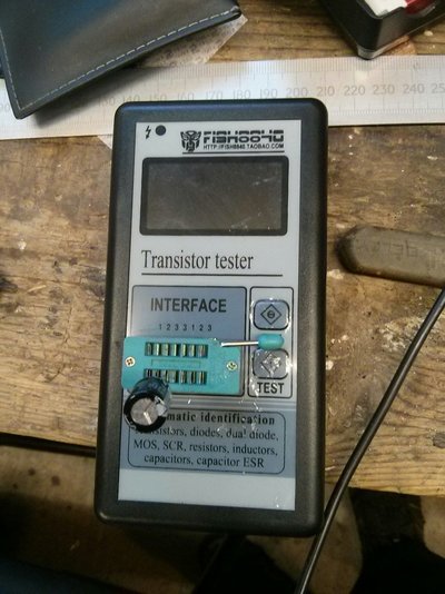
It would be unusual for the caps to have totally lost their capacitance. The capacitors may be too large - out of the range of your component tester.
Try to get hold of an analogue meter, or connect the cap to a 12v battery for a short time, then disconnect, and measure the voltage across the cap. They should hold 12v for a reasonable time. Of course, they are polarised, negative usually indicated by a stripe of "-" signs. After testing, make sure they go back into the PCB with correct polarity.
With the out-of-circuit resistance of the capacitors being in the MOhms, they are not shorted, so even if lacking in capacity they would not be the reason for the burnt resistor.
Tonyg64
Member
- Messages
- 42
- Location
- UK Warks
Thanks Eddie, I was going to try charging them on a battery and checking it that way. Out of range may be correct, Ive only ever checked smaller ones with it. If it checks out as probably not the problem I'll solder them back in and also the rectifier and try the bulb trick.
Cheers
Tony
Cheers
Tony
Tonyg64
Member
- Messages
- 42
- Location
- UK Warks
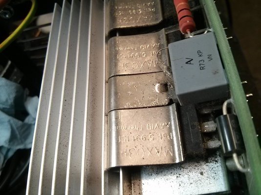
So I connected the caps to a battery and they charged up and drained very slowly (I had to introduce a bulb to drain them), so I put them back on the board. Not received the new rectifier yet so I stripped the board from the case completely. At the bottom theres some heavy duty heat sinks and quite a few "components" attached. Could anyone say what they are likely to be please?
Cheers
Tony
Cheers
Tony
")
Tonyg64
Member
- Messages
- 42
- Location
- UK Warks
Ok that could be a step in the right direction if i find a faulty one. I'm planning on desoldering all of them to find out if there are any suspect ones. Once I get a part number and find the sheet for them I can test. I'm hoping the fault doesnt lie in one of the tiny surface mount parts as that will be a pig to trace. Dont mind spending a bit if I can fix this as its been a brilliant welder. Thanks David.
Tony
Tony
As DavidL said, these will be the power transistors that turn the 325v DC into high-frequency AC. The AC may even be multi-phase. To do this, you need 4 or 6 power transistors, switched on & off by a micro controller. When IGBTs are used, each "effective" transistor is normally a single high-power device.With MOSFETs, on low-end machines there are typically several smaller transistors sharing the current in parallel, and/or the voltage in series. Without a circuit diagram, this will not be easy to diagnose, but as Seadog says, they normally just go short-circuit. The transistors may all be the same type, but sometimes they are not marked with part numbers!
The surface-mount parts will include the micro controller and gate drive and feedback circuits.
Before progressing into the inverter section, I would suggest making sure that the DC power bus is working correctly. That would involve sketching out the input circuit, confirming that the burnt resistor is in the soft-start circuit, and identifying which PCB tracks connect the 325v DC to the inverter section. Cutting those tracks would allow you to test the DC bus off-load, unaffected by any possible short-circuit in the inverter section.
Tonyg64
Member
- Messages
- 42
- Location
- UK Warks
Im not sure I can see the "path" of the DC circuit to follow it. If the transistors are shorted would they show continuity between 2 of the legs even in circuit? Or will they need to be removed anyway?. Without a diagram I'm just fishing about. Ive ordered a new solder pump station (always wanted one) so removing parts will be a lot quicker and in some ways I'm actually enjoying it. Be nice to see it weld again but if not it's not the end of the world.
Im going to apply external 12v to the clear cased relay today to see if the contacts move etc. Any tips on these to look for?
Thanks for your help guys.
Tony
Im going to apply external 12v to the clear cased relay today to see if the contacts move etc. Any tips on these to look for?
Thanks for your help guys.
Tony


