
- Forums
- Tools, Compressors and Metal Coatings
- Tools, Materials and Techniques
- Machining
- Lathes and other Machining Equipment
You are using an out of date browser. It may not display this or other websites correctly.
You should upgrade or use an alternative browser.
You should upgrade or use an alternative browser.
Archdale Milling Machine
- Thread starter Brad93
- Start date
addjunkie
Member
- Messages
- 14,328
- Location
- Northumberland. Reet oot in the sticks
You can get proper drills for such things
https://www.zoro.co.uk/shop/cutting...-threaded-shank/f/256?query=counterbore drill
https://www.zoro.co.uk/shop/cutting...-threaded-shank/f/256?query=counterbore drill
Brad93
Member
- Messages
- 19,434
- Location
- Essex, United Kingdom
You can get proper drills for such things
https://www.zoro.co.uk/shop/cutting-tools/counterbores-solid/hss-solid-counterbores-threaded-shank/f/256?query=counterbore drill
I just used a slot drill, and it worked fine.
addjunkie
Member
- Messages
- 14,328
- Location
- Northumberland. Reet oot in the sticks
Yes I agree, best if you dont turn the rotary between changing bits though, just incase. The proper bits are for when you dont have luxuries suchs as mills and DRO, or dividing heads etc.I just used a slot drill, and it worked fine.
Brad93
Member
- Messages
- 19,434
- Location
- Essex, United Kingdom
Yes I agree, best if you dont turn the rotary between changing bits though, just incase. The proper bits are for when you dont have luxuries suchs as mills and DRO, or dividing heads etc.
The rotary table is bang on as it goes. Multiple turns and it still holds the same points.
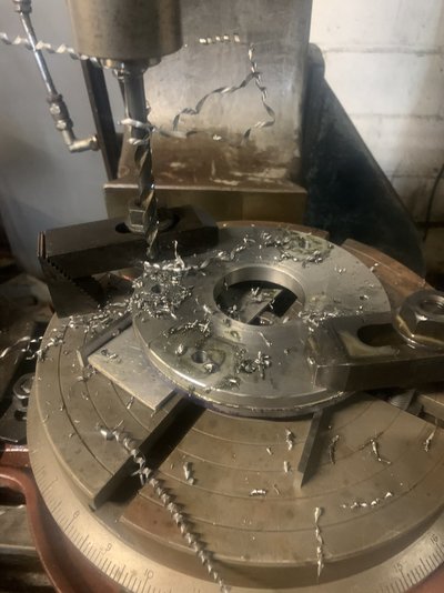
I centre drilled all the holes, then pilot drilled them all, then went through them all with an 8mm clearance drill.
Bang on every time.
I don’t have a DRO So I clocked the spindle into the centre of the table with a DTI.
Then I clocked the part roughly on the table using a thousandths indicator, then used the dti in the spindle to get it bang on.
4½ Turns of the x-axis handwheel gave me 2.25” from the centre.
Very simple stuff but it was tricky to get it right.
Bolts are 5/16” BSF. Clearance for the head of the bolts needs to be about 0.450”.
Hence wanting to counterbore with a 12mm Cutter.
Brad93
Member
- Messages
- 19,434
- Location
- Essex, United Kingdom
Well that came out **Language**ed up. I’m about 1-1.5mm out on the opposite hole. God knows whether we wasn’t completely concentric or there is some error in the rotary table. Gonna have to do it again but I may just use a transfer punch!
Matchless
I started with nothing, still have most of it left
- Messages
- 3,007
- Location
- Essex UK
Well that came out **Language** up. I’m about 1-1.5mm out on the opposite hole. God knows whether we wasn’t completely concentric or there is some error in the rotary table. Gonna have to do it again but I may just use a transfer punch!
1-1.5mm out! counts as a win in my book!

Brad93
Member
- Messages
- 19,434
- Location
- Essex, United Kingdom
There’s not really enough meat in it to be honest.Clearence size the holes itll be fine.
I went up to 9mm holes and it’s no where near. I’ve centre marked the holes with a transfer punch now, will drill it tomorrow.
I did set the whole thing up again on the mill, and the holes came out the same distance out. Can’t work it out. I’ve centred the rotary table on the mill to within 0.04mm.
Then centred the part on the table to about 0.1mm.
It must either be run out or slop in the rotary table or the holes drilled in the backplate are not concentric to the register on the backplate.
mtt.tr
Member
- Messages
- 8,467
- Location
- Essex/Suffolk border
There’s not really enough meat in it to be honest.
I went up to 9mm holes and it’s no where near. I’ve centre marked the holes with a transfer punch now, will drill it tomorrow.
I did set the whole thing up again on the mill, and the holes came out the same distance out. Can’t work it out. I’ve centred the rotary table on the mill to within 0.04mm.
Then centred the part on the table to about 0.1mm.
It must either be run out or slop in the rotary table or the holes drilled in the backplate are not concentric to the register on the backplate.
not ideal but could you not elongate your holes with a suitable endmill,
Matchless
I started with nothing, still have most of it left
- Messages
- 3,007
- Location
- Essex UK
not ideal but could you not elongate your holes with a suitable endmill,
only if you cannot find the round file!
Brad93
Member
- Messages
- 19,434
- Location
- Essex, United Kingdom
I’m gonna make the part again at some point it’s just annoying me how I keep ending up out of whack. I wasn’t super happy with the fitment of the register it had a thou or two slop in it.not ideal but could you not elongate your holes with a suitable endmill,
This is good practice and saves trying to make a proper part and having this happen.
It’s most likely user error, but I’m struggling to see where unless it’s a combination of errors. I’ve got about 0.1mm of play in the spindle and quill, I’ve got 0.04mm on the rotary table being centred, less than 0.1mm when the part is on the rotary table, x and y axis locked off, actuating the lock on the rotary table can move the table another 0.1mm. So worst cast 0.25mm-0.35mm of error. I’m drilling +1mm holes and still not lining up.
Matchless
I started with nothing, still have most of it left
- Messages
- 3,007
- Location
- Essex UK
I had to mill and drill a blanking plate for the Rover Metro petrol tank I fitted a couple of weeks ago, you can only get Rover 100 pattern tanks and they have a big hole in the top for an injection pump, said Rover Metro was a 1.1 carb model, ok, I found a bit steel, already round, set it up on the rotary table, lined the slot drill up with the sharpie mark I had made, set it to the No.6 mark, drill, click, drill, click, repeat as required, counter bore as the studs welded to the tank are quite short, make a suitable gasket, find one hole is offset......... well you cannot see it now as it was on top of the tank!
mtt.tr
Member
- Messages
- 8,467
- Location
- Essex/Suffolk border
i would guess backlash brad, when going in the opposite direction just before you move put a dit against the axis you want to move, as soon as you see the dial move you know youve taken up the back lash, and kept track of where the table is
addjunkie
Member
- Messages
- 14,328
- Location
- Northumberland. Reet oot in the sticks
What I do, for such things, is not worry about centering the table. Set bit up over the first hole. Drill , change bits etc and complete, turn table to next hole and repeat. Always turn in the same direction too. But I do lock the x and y axis to remove as much error as possible.
There is error in everything, all you can do is minimise it.
How are you centering the work onto the rotary table
There is error in everything, all you can do is minimise it.
How are you centering the work onto the rotary table
daedalusminos
Member
- Messages
- 2,429
- Location
- Norwich
Will keep an eye out. It’s Quantumike month next month
Any idea what the typical MSC offer price is for a 1-2" QuantuMike -
