- Forums
- Tools, Compressors and Metal Coatings
- Tools, Materials and Techniques
- Machining
- Lathes and other Machining Equipment
You are using an out of date browser. It may not display this or other websites correctly.
You should upgrade or use an alternative browser.
You should upgrade or use an alternative browser.
Tos FN22 milling machine (Deckel clone)
- Thread starter Pete.
- Start date
Pete.
Member
- Messages
- 15,066
- Location
- Kent, UK
Another job ticked off the list. The gib that fixes the horizontal arbor outboard support bracket to the over-arm was missing. Hardly surprising since it's not fixed in place. I had to make a new one.
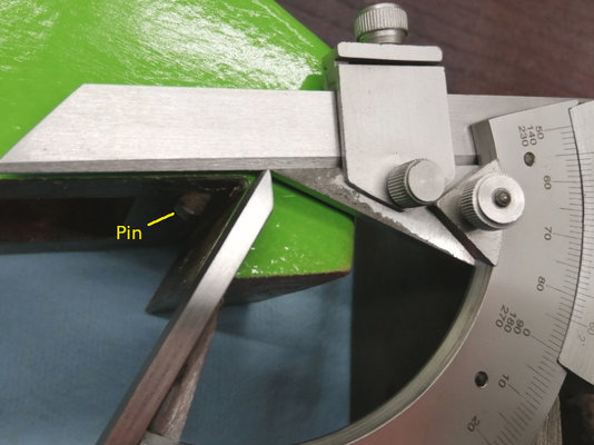
First to measure the dovetail angle. Dovetails can be any angle though most people assume they are 60 degrees. On the TOS they are 55 degrees as the pic shows. Also in the pic is shown a retaining pin for the gib which is to stop it sliding out when you're adjusting the position.
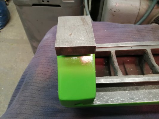
Luckily I had a piece of scrap cast iron knocking about that was just the right size.
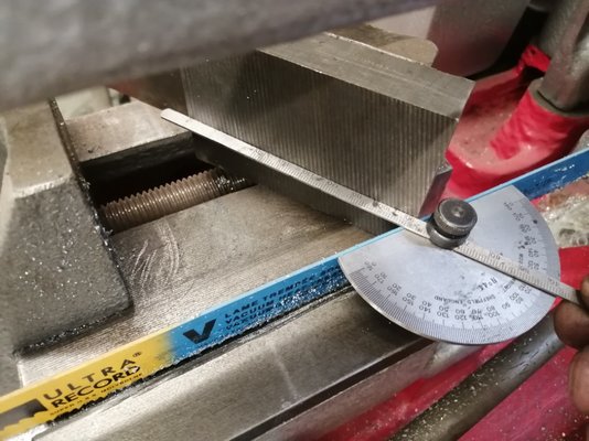
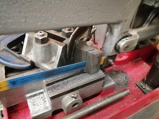
I set the piece up in the mechanical hacksaw. Because of the angle I had to G-clamp the jaws together to keep it held securely.
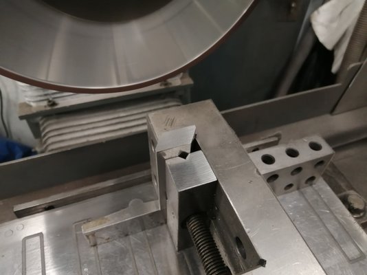
Once the shape was cut I ground it to size on 8 sides on my surface grinder
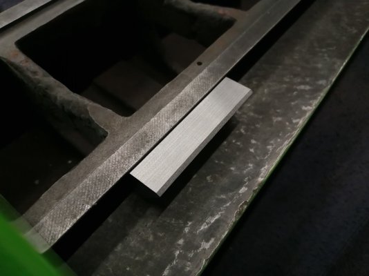
Fits nice in the dovetail
Now the tricky bit is how to drill the holes for the pin and the locking bolt. The pin was easy to do, I just eyeballed the location and marked it with a black marker. Because the pin was set parallel to the dovetail veeI put the gib in a vice and used a small slot drill to make the hole.
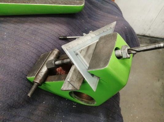
The locking bolt hole was another matter. With no reference surface to work from and not willing to clamp the painted parts up in the milling machine I had to get creative. So I cobbled up a jacking screw from bits in my milling machine clamp kit and some scrap metal.
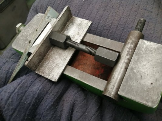
The plastic set square is a sacrificial spacer that happened to be the perfect thickness for the gap between the gib and the support block. I needed a way to guide the drill so it would cut into the gib at an angle to the face without wandering so I drilled a 8.8 bolt and used it as a drilling guide. Worked perfectly well just drilling it with my battery drill.
Here's the gib strip sitting in the opposite vee way just to show the two drilled holes.
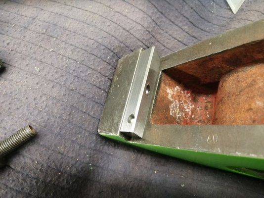
And here it is assembled
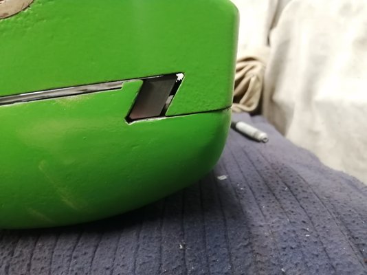
The only thing left to do is make a new cover plate for the underside of the over-arm as the original is missing, and then give both pieces another coat of paint because out of all the parts I sprayed, these came out the worst.
First to measure the dovetail angle. Dovetails can be any angle though most people assume they are 60 degrees. On the TOS they are 55 degrees as the pic shows. Also in the pic is shown a retaining pin for the gib which is to stop it sliding out when you're adjusting the position.

Luckily I had a piece of scrap cast iron knocking about that was just the right size.

I set the piece up in the mechanical hacksaw. Because of the angle I had to G-clamp the jaws together to keep it held securely.


Once the shape was cut I ground it to size on 8 sides on my surface grinder

Fits nice in the dovetail

Now the tricky bit is how to drill the holes for the pin and the locking bolt. The pin was easy to do, I just eyeballed the location and marked it with a black marker. Because the pin was set parallel to the dovetail veeI put the gib in a vice and used a small slot drill to make the hole.
The locking bolt hole was another matter. With no reference surface to work from and not willing to clamp the painted parts up in the milling machine I had to get creative. So I cobbled up a jacking screw from bits in my milling machine clamp kit and some scrap metal.

The plastic set square is a sacrificial spacer that happened to be the perfect thickness for the gap between the gib and the support block. I needed a way to guide the drill so it would cut into the gib at an angle to the face without wandering so I drilled a 8.8 bolt and used it as a drilling guide. Worked perfectly well just drilling it with my battery drill.

Here's the gib strip sitting in the opposite vee way just to show the two drilled holes.

And here it is assembled

The only thing left to do is make a new cover plate for the underside of the over-arm as the original is missing, and then give both pieces another coat of paint because out of all the parts I sprayed, these came out the worst.
Pete.
Member
- Messages
- 15,066
- Location
- Kent, UK
Rebuilding the slotting head drive mechanism. I had to make a whole new shaft because the original one was bent on the end and my attempt to straighten it put it out of round. There was a big chunk on the corner of the conrod which I had to file out so I think that perhaps it had come loose and struck the housing bending the shaft.
Whomever designed or built this slotting head had a curious sense of humour. The shaft has four diameters - 20mm, 25mm, 30mm and 1". The crank end has a 25mm bore and 5/16" keyway. The big drive gear has a 20mm bore and 6mm keyway but the shaft was keyed 1/4" so they fitted a stepped key. Finally that gear was secured by a 5/16" BSF bolt - on a metric machine! All very strange.
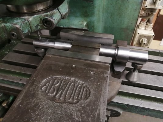
Anyway I turned the shaft, cut a circlip groove in it then set it up in my Herbert mill. Just held it in my vice with a vee block and a jack under each end I clocked it level with a dial indicator and set about cutting the keyways.
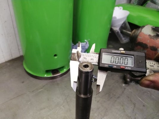
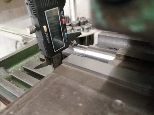
An easy way to check the depth of keyways if you're copying a piece:
5/16" keyway for the crank end.
Shaft fitted with new bearings. I had to put a gently knurl on it because I changed the insert on my lathe tool and over-shot the cut. The bearing didn't rattle but was loose enough to slide off and I wasn't happy with that. I didn't want to use loctite just in case it has to come off again so I knurled it and pressed it onto the knurl.
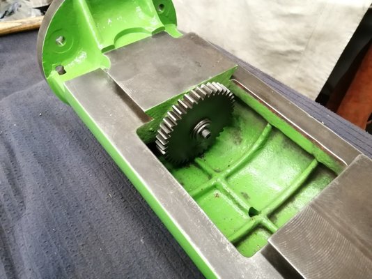
Drive gear fitted with it's BSF fastener
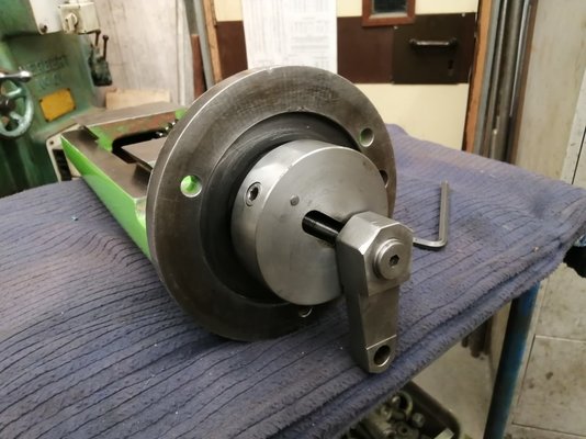
End crank fitted on the working end. This photo shows the method of adjustment. You loosen the 8mm allen key on the front then turn the one on the edge of the crank to adjust the throw of the crank and therefore the stroke of the slotting slide.
Next job is to sort out the sliding wys of the slide itself and then get it ready for painting.
Whomever designed or built this slotting head had a curious sense of humour. The shaft has four diameters - 20mm, 25mm, 30mm and 1". The crank end has a 25mm bore and 5/16" keyway. The big drive gear has a 20mm bore and 6mm keyway but the shaft was keyed 1/4" so they fitted a stepped key. Finally that gear was secured by a 5/16" BSF bolt - on a metric machine! All very strange.
Anyway I turned the shaft, cut a circlip groove in it then set it up in my Herbert mill. Just held it in my vice with a vee block and a jack under each end I clocked it level with a dial indicator and set about cutting the keyways.

An easy way to check the depth of keyways if you're copying a piece:


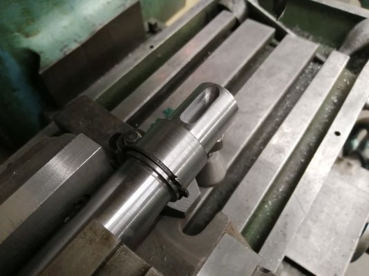
5/16" keyway for the crank end.

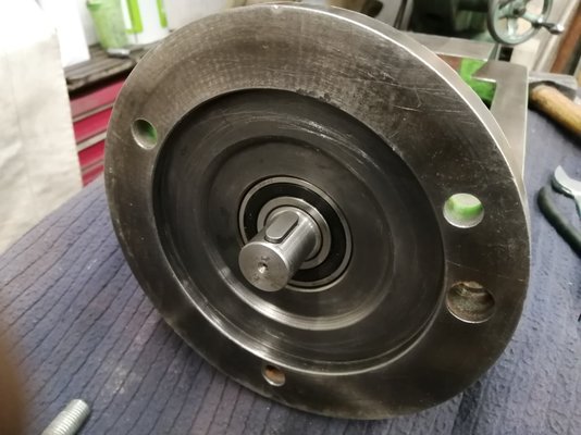
Shaft fitted with new bearings. I had to put a gently knurl on it because I changed the insert on my lathe tool and over-shot the cut. The bearing didn't rattle but was loose enough to slide off and I wasn't happy with that. I didn't want to use loctite just in case it has to come off again so I knurled it and pressed it onto the knurl.

Drive gear fitted with it's BSF fastener

End crank fitted on the working end. This photo shows the method of adjustment. You loosen the 8mm allen key on the front then turn the one on the edge of the crank to adjust the throw of the crank and therefore the stroke of the slotting slide.

Next job is to sort out the sliding wys of the slide itself and then get it ready for painting.
roofman
Purveyor of fine English buckets and mops
- Messages
- 13,038
- Location
- North West with water on 3 sides
Thats a nice little tip about knurling a shaft if you have cut too much off and its slack...normally i would center punch but a heavy knurl makes much more senseRebuilding the slotting head drive mechanism. I had to make a whole new shaft because the original one was bent on the end and my attempt to straighten it put it out of round. There was a big chunk on the corner of the conrod which I had to file out so I think that perhaps it had come loose and struck the housing bending the shaft.
Whomever designed or built this slotting head had a curious sense of humour. The shaft has four diameters - 20mm, 25mm, 30mm and 1". The crank end has a 25mm bore and 5/16" keyway. The big drive gear has a 20mm bore and 6mm keyway but the shaft was keyed 1/4" so they fitted a stepped key. Finally that gear was secured by a 5/16" BSF bolt - on a metric machine! All very strange.
Anyway I turned the shaft, cut a circlip groove in it then set it up in my Herbert mill. Just held it in my vice with a vee block and a jack under each end I clocked it level with a dial indicator and set about cutting the keyways.
View attachment 325155
An easy way to check the depth of keyways if you're copying a piece:
View attachment 325156
View attachment 325157
5/16" keyway for the crank end.
View attachment 325158
Shaft fitted with new bearings. I had to put a gently knurl on it because I changed the insert on my lathe tool and over-shot the cut. The bearing didn't rattle but was loose enough to slide off and I wasn't happy with that. I didn't want to use loctite just in case it has to come off again so I knurled it and pressed it onto the knurl.
View attachment 325159
Drive gear fitted with it's BSF fastener
View attachment 325160
End crank fitted on the working end. This photo shows the method of adjustment. You loosen the 8mm allen key on the front then turn the one on the edge of the crank to adjust the throw of the crank and therefore the stroke of the slotting slide.
View attachment 325161
Next job is to sort out the sliding wys of the slide itself and then get it ready for painting.

Hood
Member
- Messages
- 17,984
- Location
- Carnoustie, Scotland
Often have to do that for cutlass bearings in the boats when the tubes have been damaged by a cutlass bearing spinning. Only other option is an oversized cutlass and turn it down but that can get expensive so if it is not too bad knurling does the trick.Thats a nice little tip about knurling a shaft if you have cut too much off and its slack...normally i would center punch but a heavy knurl makes much more sense
Pete.
Member
- Messages
- 15,066
- Location
- Kent, UK
I decided that the ways were too small, too awkward, too gouged and had a very awkwardly placed oiling groove to try to scrape them. My milling machine is short on the travel required to mill the dovetails in one pass but my surface grinder has just about enough travel so I decided to see if I could grind the damage out. I have a old but very good quality tilting table which I was just about able to mount on the grinder and the slide just about fitted onto that.
Here's the setup (this was taken later after I dressed the wheel and did the grinding but it's the only photo I got that shows it all).
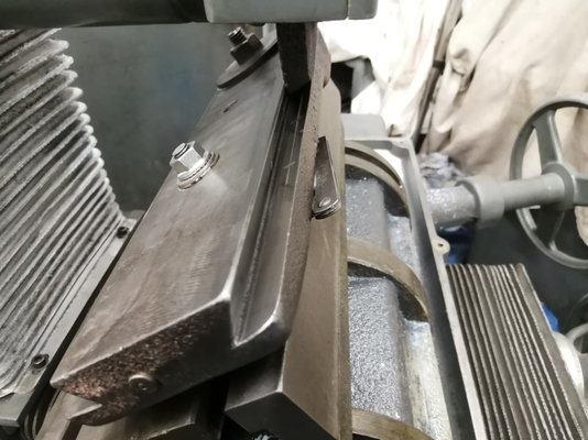
The setup took a lot of time and careful measuring. The table tilt axis had to be dead parallel to the travel, the top had to be dead parallel to the grinder table. The slide being ground then had to be mounted parallel to the tilting table AND the travel of the grinder table and after all of that was achieved the slide was tilted over to 35 degrees which put the 55 degree dovetail dead vertical and all the measurements checked again.
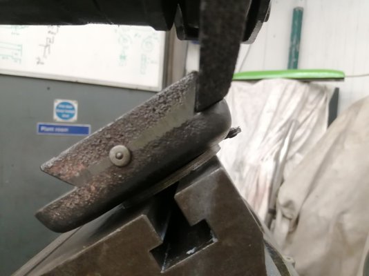
Next I had to dress the grinder wheel to cut the vee both sides in one setup. I learned a trick from Brian at Slideway services when he told me that he manually dressed wheels using a sliding block on a sine table and moved the diamond by hand so I utilised that trick here too. I set a square across the bottom face of the slide, milled a flat edge on my dressing diamond holder then used that setup to cut the wheel the exact same angle as the slideway.
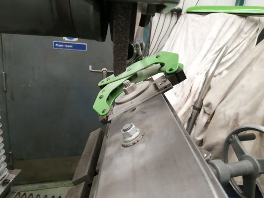
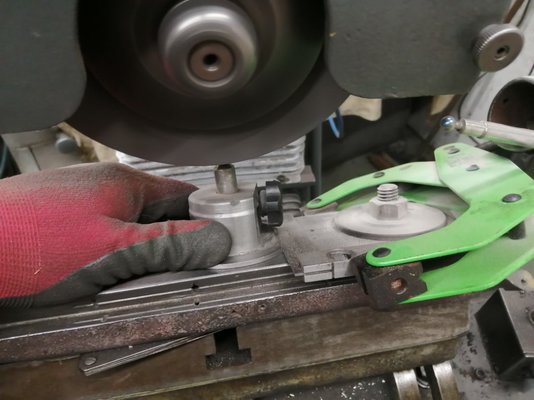
By the way I don't have big fat John Merrick hands I'm bridging over a hold-down bolt
The back of the wheel I dressed using the z-axiz by mounting the diamond on a mag mount.
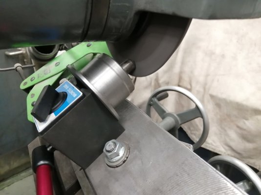
This all meant that the two faces on the wheel are dressed exactly to the angle of the two faces for grinding on the part. To be honest grinding the vertical face in such a fashion isn't the best of practices and I found that it certainly highlights the 'budget' nature of my milling machine. Just the tiny end float in the spindle bearings was enough to cause me problems and it wasn't helped by the slow rate I had to dress the wheel at which meant that it wasn't very open. I had a couple of scorch marks in the face after grinding just from the rubbing of the wheel. It'll be OK after scraping though, the whole idea was to get me to a place where it wasn't going to be a completely frustrating job of scraping especially since the slide does not have a relief groove in the bottom of the vee.
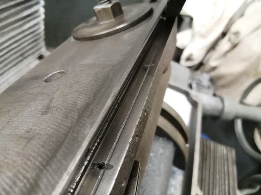
I ground the ways on one side of the slide enough to get rid of the galling damage. Tomorrow I'm going to have to carefully reverse the setup and do it all again on the other side, then it will be pretty close, easily within comfortable scraping-in distance, I hope.
Here's the setup (this was taken later after I dressed the wheel and did the grinding but it's the only photo I got that shows it all).

The setup took a lot of time and careful measuring. The table tilt axis had to be dead parallel to the travel, the top had to be dead parallel to the grinder table. The slide being ground then had to be mounted parallel to the tilting table AND the travel of the grinder table and after all of that was achieved the slide was tilted over to 35 degrees which put the 55 degree dovetail dead vertical and all the measurements checked again.
Next I had to dress the grinder wheel to cut the vee both sides in one setup. I learned a trick from Brian at Slideway services when he told me that he manually dressed wheels using a sliding block on a sine table and moved the diamond by hand so I utilised that trick here too. I set a square across the bottom face of the slide, milled a flat edge on my dressing diamond holder then used that setup to cut the wheel the exact same angle as the slideway.


By the way I don't have big fat John Merrick hands I'm bridging over a hold-down bolt

The back of the wheel I dressed using the z-axiz by mounting the diamond on a mag mount.

This all meant that the two faces on the wheel are dressed exactly to the angle of the two faces for grinding on the part. To be honest grinding the vertical face in such a fashion isn't the best of practices and I found that it certainly highlights the 'budget' nature of my milling machine. Just the tiny end float in the spindle bearings was enough to cause me problems and it wasn't helped by the slow rate I had to dress the wheel at which meant that it wasn't very open. I had a couple of scorch marks in the face after grinding just from the rubbing of the wheel. It'll be OK after scraping though, the whole idea was to get me to a place where it wasn't going to be a completely frustrating job of scraping especially since the slide does not have a relief groove in the bottom of the vee.

I ground the ways on one side of the slide enough to get rid of the galling damage. Tomorrow I'm going to have to carefully reverse the setup and do it all again on the other side, then it will be pretty close, easily within comfortable scraping-in distance, I hope.

Brad93
Member
- Messages
- 19,430
- Location
- Essex, United Kingdom
In future you're welcome to borrow my crown sine table.I decided that the ways were too small, too awkward, too gouged and had a very awkwardly placed oiling groove to try to scrape them. My milling machine is short on the travel required to mill the dovetails in one pass but my surface grinder has just about enough travel so I decided to see if I could grind the damage out. I have a old but very good quality tilting table which I was just about able to mount on the grinder and the slide just about fitted onto that.
Here's the setup (this was taken later after I dressed the wheel and did the grinding but it's the only photo I got that shows it all).
View attachment 325194
The setup took a lot of time and careful measuring. The table tilt axis had to be dead parallel to the travel, the top had to be dead parallel to the grinder table. The slide being ground then had to be mounted parallel to the tilting table AND the travel of the grinder table and after all of that was achieved the slide was tilted over to 35 degrees which put the 55 degree dovetail dead vertical and all the measurements checked again.
Next I had to dress the grinder wheel to cut the vee both sides in one setup. I learned a trick from Brian at Slideway services when he told me that he manually dressed wheels using a sliding block on a sine table and moved the diamond by hand so I utilised that trick here too. I set a square across the bottom face of the slide, milled a flat edge on my dressing diamond holder then used that setup to cut the wheel the exact same angle as the slideway.
View attachment 325191
View attachment 325192
By the way I don't have big fat John Merrick hands I'm bridging over a hold-down bolt
The back of the wheel I dressed using the z-axiz by mounting the diamond on a mag mount.
View attachment 325190
This all meant that the two faces on the wheel are dressed exactly to the angle of the two faces for grinding on the part. To be honest grinding the vertical face in such a fashion isn't the best of practices and I found that it certainly highlights the 'budget' nature of my milling machine. Just the tiny end float in the spindle bearings was enough to cause me problems and it wasn't helped by the slow rate I had to dress the wheel at which meant that it wasn't very open. I had a couple of scorch marks in the face after grinding just from the rubbing of the wheel. It'll be OK after scraping though, the whole idea was to get me to a place where it wasn't going to be a completely frustrating job of scraping especially since the slide does not have a relief groove in the bottom of the vee.
View attachment 325193
I ground the ways on one side of the slide enough to get rid of the galling damage. Tomorrow I'm going to have to carefully reverse the setup and do it all again on the other side, then it will be pretty close, easily within comfortable scraping-in distance, I hope.
View attachment 325195
Pete.
Member
- Messages
- 15,066
- Location
- Kent, UK
Thanks Brad I appreciate itIn future you're welcome to borrow my crown sine table.

Well I've finished grinding the slide and I'm very happy with how it's come out. Ii spent a long time taking measurements and setting the slide up using a tenth-reading DTI on the side I had already ground. Then I just repeated the process to grind the second side.
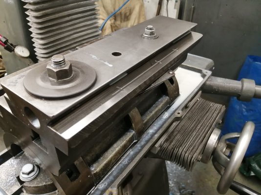
The upper vee way in this pic is the one with the most wear. It was not only heavily worn but also bedly scored. Grinding out the scores has meant that I have also ground out the remainder of the oiling groove. I will have to put that groove back in with the corner of an end mill.
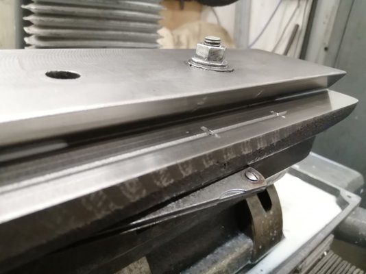
The proof of the pudding is in measuring the width of the dovetail. I put ground pins in the vees and measured across the pins. 0.02mm difference is better than I ever hoped for so I'll take that

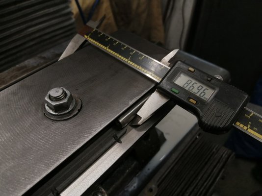
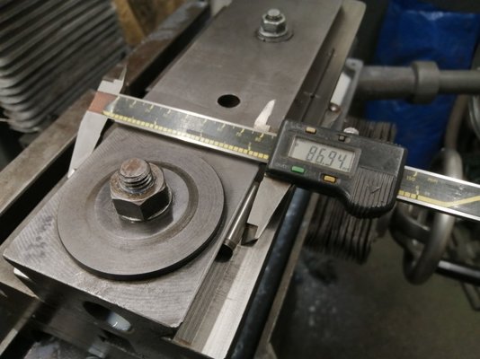
The down-side of grinding the slide's way is that it lowers the overall height slightly. When I put it back together I found that it was rubbing on the paint of the housing.
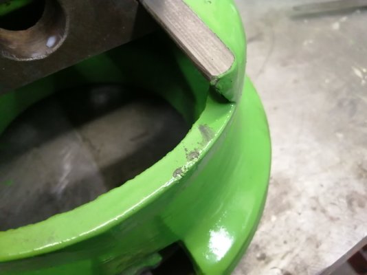
I knocked the paint off with a scraper and now I can get a 5 thou feeler gauge in the gap

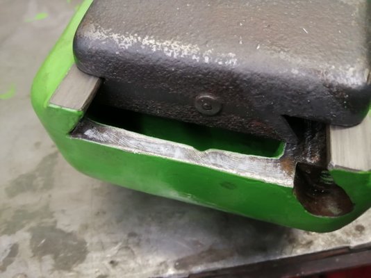
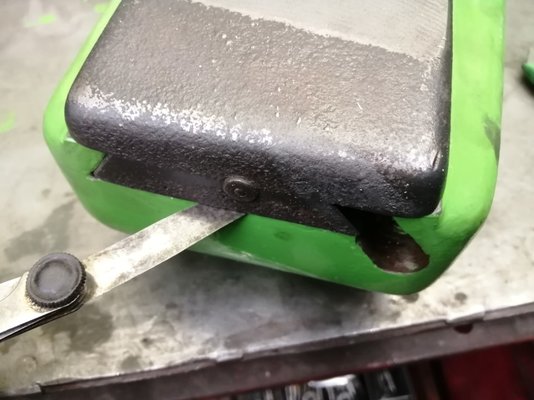
All that's left is to scrape those slides, cut a new oiling groove and figure out a way to shim the gib.
Pete.
Member
- Messages
- 15,066
- Location
- Kent, UK
Pete.
Member
- Messages
- 15,066
- Location
- Kent, UK
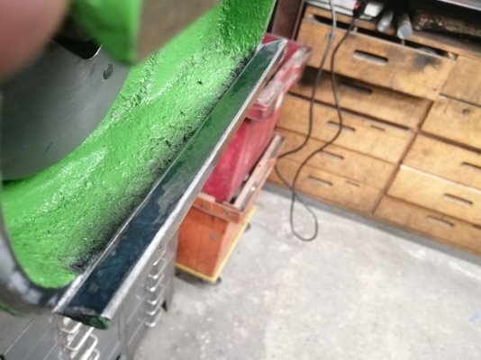
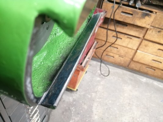
Today scraped the inside ways of the slotting head. Here it was after a few passes. Lot of wear in the middle opposite where the slide was badly galled.
A couple of rounds of scraping and it was coming in nicely. I continued until the blue joined in the middle.
Last thing to do is sort out the gib. Gibs only wear one side I put it on my grinder to grind the side that does the work. It's a tapered gib with IIRC 1:100 taper. In order to grind it back to the correct angle I packed up one side of my mag chuck and used a dial indicator to make both ends the same height. The taper was not reading consistantly all along and when I ground it a couple of times I found out why.
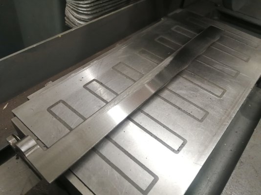
A big dip in the middle, once again where the slide had started to pick up and gall the surface. Anyway, I ground the gib about 10 thou and as expected when I released the mag chuck it sprung up in a lovely curve. To bring the curve back down I flipped it over and ground the other side a bit. This reversed the curve but any curve in a gib is undesirable if you're trying to scrape it in and I couldn't keep grinding away at the gib since I was close approaching the correct thickness to add my way liner.
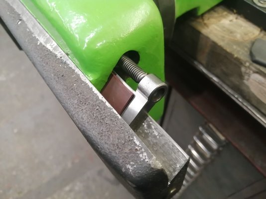
You have to be extra careful with tapered gibs because the difference in taper thickness from one end of the adjustment to the other is only a few thou. It's much better to make the gib extra-long and then cut it off to length once it's scraped in but since I am repairing this gib I have to go careful and get it right. I have some 60 thou way liner (similar to turcite, rulon etc just a different manufacturer) so I cut a bit off and used it as a gauge to grind the gib to thickness. Here it is after grinding is finished but before I've taken the bend out.
Straightening a piece of cast iron is easier than you'd think. All you have to do is put the part on a flat surface and peen the top of the side you want to come upwards. Peening stretches the surface causing it to lengthen so it rises up where you are hitting it. I put the gib on a piece of card and used my smallest ball pein hammer to lightly tap the top of the gib in the middle. Before I started the gib was spinning like a top. A couple of minutes of light peening and the middle had started to lift as it was now bending upwards instead of downwards. If you ever have to do this, check very often because it happens really quickly and it's easy to over-shoot.
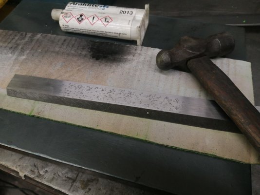
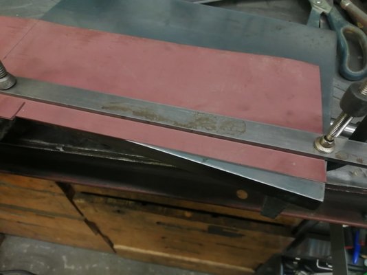
Naturally you would not want to fill a working way with hammer marks but in this case it doesn't matter because it'll be under the glued-on piece of way liner. I cut the way liner with a knife just smaller than the falt face of the gib. I roughed the surface up heavily with the edge of a half-round file in criss-cross pattern and glued it on with Araldite 2013. This is a very high strength glue and the little tube in the pic above is nearly 30 quid.
Once it was glued on I oiled up the ways of the slide and housing and gently hammered the gib into the gap to allow the glue to cure overnight.
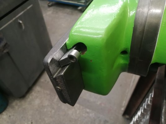
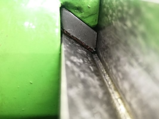

A couple of rounds of scraping and it was coming in nicely. I continued until the blue joined in the middle.

Last thing to do is sort out the gib. Gibs only wear one side I put it on my grinder to grind the side that does the work. It's a tapered gib with IIRC 1:100 taper. In order to grind it back to the correct angle I packed up one side of my mag chuck and used a dial indicator to make both ends the same height. The taper was not reading consistantly all along and when I ground it a couple of times I found out why.

A big dip in the middle, once again where the slide had started to pick up and gall the surface. Anyway, I ground the gib about 10 thou and as expected when I released the mag chuck it sprung up in a lovely curve. To bring the curve back down I flipped it over and ground the other side a bit. This reversed the curve but any curve in a gib is undesirable if you're trying to scrape it in and I couldn't keep grinding away at the gib since I was close approaching the correct thickness to add my way liner.
You have to be extra careful with tapered gibs because the difference in taper thickness from one end of the adjustment to the other is only a few thou. It's much better to make the gib extra-long and then cut it off to length once it's scraped in but since I am repairing this gib I have to go careful and get it right. I have some 60 thou way liner (similar to turcite, rulon etc just a different manufacturer) so I cut a bit off and used it as a gauge to grind the gib to thickness. Here it is after grinding is finished but before I've taken the bend out.

Straightening a piece of cast iron is easier than you'd think. All you have to do is put the part on a flat surface and peen the top of the side you want to come upwards. Peening stretches the surface causing it to lengthen so it rises up where you are hitting it. I put the gib on a piece of card and used my smallest ball pein hammer to lightly tap the top of the gib in the middle. Before I started the gib was spinning like a top. A couple of minutes of light peening and the middle had started to lift as it was now bending upwards instead of downwards. If you ever have to do this, check very often because it happens really quickly and it's easy to over-shoot.

Naturally you would not want to fill a working way with hammer marks but in this case it doesn't matter because it'll be under the glued-on piece of way liner. I cut the way liner with a knife just smaller than the falt face of the gib. I roughed the surface up heavily with the edge of a half-round file in criss-cross pattern and glued it on with Araldite 2013. This is a very high strength glue and the little tube in the pic above is nearly 30 quid.

Once it was glued on I oiled up the ways of the slide and housing and gently hammered the gib into the gap to allow the glue to cure overnight.


123hotchef
Member
- Messages
- 14,395
- Location
- Kent
wow looking good now not long until its earning its keep!
what material is the way liner?
what material is the way liner?
Interesting to see your gibs are cast iron. The ones on my Town Woodhouse are the softest steel you could find, they scraped like butter, and both the short (apron) and long (table) were bent. And so actually, was the 5 inch chunky one in the top one in the knee, but that had been violently removed from its home...Today scraped the inside ways of the slotting head. Here it was after a few passes. Lot of wear in the middle opposite where the slide was badly galled.
View attachment 325527
A couple of rounds of scraping and it was coming in nicely. I continued until the blue joined in the middle.
View attachment 325528
Last thing to do is sort out the gib. Gibs only wear one side I put it on my grinder to grind the side that does the work. It's a tapered gib with IIRC 1:100 taper. In order to grind it back to the correct angle I packed up one side of my mag chuck and used a dial indicator to make both ends the same height. The taper was not reading consistantly all along and when I ground it a couple of times I found out why.
View attachment 325529
A big dip in the middle, once again where the slide had started to pick up and gall the surface. Anyway, I ground the gib about 10 thou and as expected when I released the mag chuck it sprung up in a lovely curve. To bring the curve back down I flipped it over and ground the other side a bit. This reversed the curve but any curve in a gib is undesirable if you're trying to scrape it in and I couldn't keep grinding away at the gib since I was close approaching the correct thickness to add my way liner.
You have to be extra careful with tapered gibs because the difference in taper thickness from one end of the adjustment to the other is only a few thou. It's much better to make the gib extra-long and then cut it off to length once it's scraped in but since I am repairing this gib I have to go careful and get it right. I have some 60 thou way liner (similar to turcite, rulon etc just a different manufacturer) so I cut a bit off and used it as a gauge to grind the gib to thickness. Here it is after grinding is finished but before I've taken the bend out.
View attachment 325531
Straightening a piece of cast iron is easier than you'd think. All you have to do is put the part on a flat surface and peen the top of the side you want to come upwards. Peening stretches the surface causing it to lengthen so it rises up where you are hitting it. I put the gib on a piece of card and used my smallest ball pein hammer to lightly tap the top of the gib in the middle. Before I started the gib was spinning like a top. A couple of minutes of light peening and the middle had started to lift as it was now bending upwards instead of downwards. If you ever have to do this, check very often because it happens really quickly and it's easy to over-shoot.
View attachment 325530
Naturally you would not want to fill a working way with hammer marks but in this case it doesn't matter because it'll be under the glued-on piece of way liner. I cut the way liner with a knife just smaller than the falt face of the gib. I roughed the surface up heavily with the edge of a half-round file in criss-cross pattern and glued it on with Araldite 2013. This is a very high strength glue and the little tube in the pic above is nearly 30 quid.
View attachment 325532
Once it was glued on I oiled up the ways of the slide and housing and gently hammered the gib into the gap to allow the glue to cure overnight.
View attachment 325533
View attachment 325534
Took a press and some patients to get that within scraping range. I shimmed them all with shim steel glued on.
Pete.
Member
- Messages
- 15,066
- Location
- Kent, UK
Interesting to see your gibs are cast iron. The ones on my Town Woodhouse are the softest steel you could find, they scraped like butter, and both the short (apron) and long (table) were bent. And so actually, was the 5 inch chunky one in the top one in the knee, but that had been violently removed from its home...
Took a press and some patients to get that within scraping range. I shimmed them all with shim steel glued on.
I have no aversion to shimming a gib but if you look at how this one is retained it has a cast-on lug with a hole in it that is for the adjuster screw. Shimming behind it mis-aligns the hole. I could have drilled the hole out bigger but because of the amount of wear and subsequent grinding I felt it was a bit too far so I went the other way instead.
pressbrake1
Member
- Messages
- 5,776
- Location
- Essex
Is that a phenolic material you’ve used, I can’t see
Pete.
Member
- Messages
- 15,066
- Location
- Kent, UK
Is that a phenolic material you’ve used, I can’t see
It's Marlon
Pete.
Member
- Messages
- 15,066
- Location
- Kent, UK
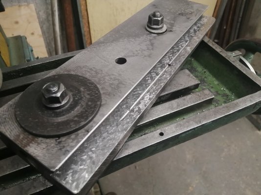
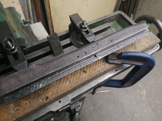
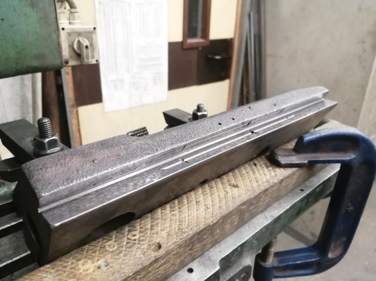
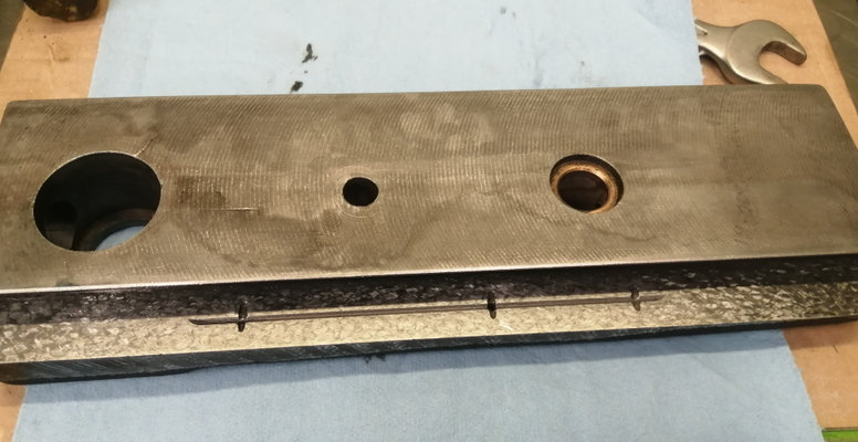
Because the grinder is set up for the proper taper angle I decided to get making the missing gibs for the dividing attachment overarm. One is about 100mm long, 3.5mm one end and 4.5mm the other (I measured the end gaps with a thin tapered wedge painted with magic marker). The other is about 235mm long.
I started with the small one, found some 3/16" gauge plate and milled the edges to the 55 degree angle so they fit in the dovetail. Didn't get any pics of that sorry
Then I ground in the taper with my surface grinder. As expected, it bent.
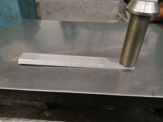
Now being a steel gib I could have just based it flat but I thought I'd have another go at hammer straightening. It's steel and a lot thinner so took a bit more but it worked just as well.
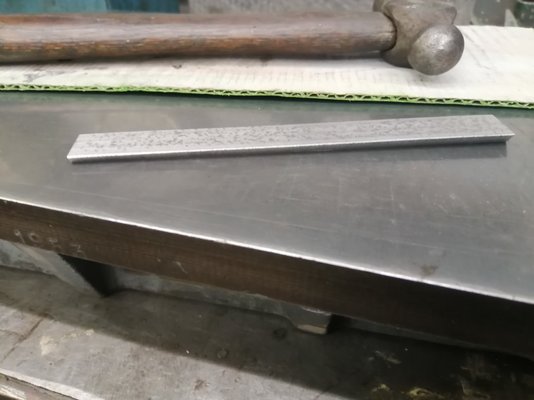
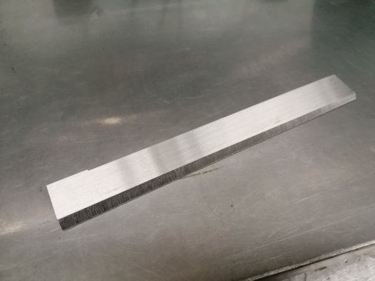
As it happens, grinding the other side bent it the other way so I kept flipping it over and grinding each side a bit until it was the correct thickness and more or less straight.
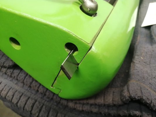
Here it is inserted in the tailstock. Tomorrow I will decide whether to try to add on the same adjusting collar as the slotting head gib had or just use a collared adjusted and slot the gib. Probably, I will just slot the gib so it doesn't get all messed up by welding or brazing.
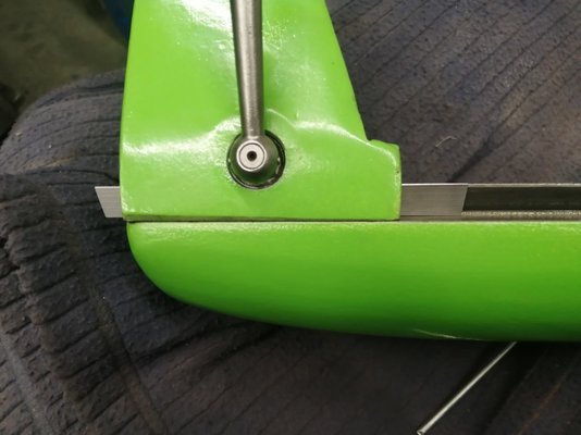
Here you can see ehy you make them over-length. It's easier to cut them down to size than it is to re-make one because you over-shot the mark.
I started with the small one, found some 3/16" gauge plate and milled the edges to the 55 degree angle so they fit in the dovetail. Didn't get any pics of that sorry

Then I ground in the taper with my surface grinder. As expected, it bent.

Now being a steel gib I could have just based it flat but I thought I'd have another go at hammer straightening. It's steel and a lot thinner so took a bit more but it worked just as well.

As it happens, grinding the other side bent it the other way so I kept flipping it over and grinding each side a bit until it was the correct thickness and more or less straight.

Here it is inserted in the tailstock. Tomorrow I will decide whether to try to add on the same adjusting collar as the slotting head gib had or just use a collared adjusted and slot the gib. Probably, I will just slot the gib so it doesn't get all messed up by welding or brazing.

Here you can see ehy you make them over-length. It's easier to cut them down to size than it is to re-make one because you over-shot the mark.

Windy Miller
Semi-Professional Potterer!
- Messages
- 3,704
- Location
- North Kent, UK
Absolutely fascinating - it’s a whole new world!

