Hi,
I have a fairly cheap MIG (see this post for details). As I noted, the wire feed speed seemed a bit variable. We noticed that the feed roller groove didn't line up, so we tweaked it a bit to get it working more smoothly. This seemed to make it worse! (we figure the extra load on the motor was masking the variable speed control...).
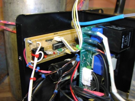
Anyway, investigating the circuitry showed that the wire feeder is fed power from the positive output of the welding supply. This goes into a very crude PWM generator (basically a transistor with variable bias) to adjust the speed.
To my mind, this means the wire speed will fluctuate with changes in the arc (which would cause changes in the electrode voltage), which in turn would make the arc more unstable. I've noted that I can hear the motor speed changing during welding on low settings.
Have they used this set-up juct to save putting another auxillary transformer in the machine to run the feed motor? Or is there a reason why you would want the feed motor voltage to be affected by the electrode voltage?
For a test, I cut the wires to the feed motor and wired them into an adjustable bench power supply (0-25 volts) through an automotove relay (turned on by the original feed motor voltage). This worked rather well and I think it welded better with the more smooth feed motor voltage. I'm contemplating building a new regulated power supply and speed control to run the motor, totally independant of the arc voltage. Just wondering if this is going to cause any other problems?
I'm also interested in capacitiors which I see people have mentioned here. My welder has a diode stack and a big inductor in series with the negative electrode but I can't see any big caps (although it shows one on the circuit diagram). What effect would smoothing caps have on my welding? Would it make the lower power settings maintain an arc better?
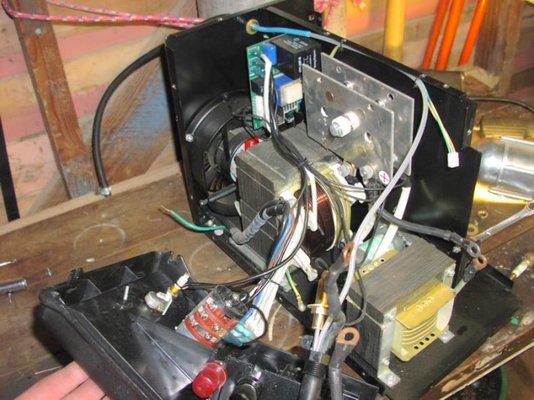
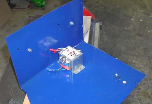
Sorry about the long post - thanks for suggestions! I'll post some pics of the inside soon.
I have a fairly cheap MIG (see this post for details). As I noted, the wire feed speed seemed a bit variable. We noticed that the feed roller groove didn't line up, so we tweaked it a bit to get it working more smoothly. This seemed to make it worse! (we figure the extra load on the motor was masking the variable speed control...).
Anyway, investigating the circuitry showed that the wire feeder is fed power from the positive output of the welding supply. This goes into a very crude PWM generator (basically a transistor with variable bias) to adjust the speed.
To my mind, this means the wire speed will fluctuate with changes in the arc (which would cause changes in the electrode voltage), which in turn would make the arc more unstable. I've noted that I can hear the motor speed changing during welding on low settings.
Have they used this set-up juct to save putting another auxillary transformer in the machine to run the feed motor? Or is there a reason why you would want the feed motor voltage to be affected by the electrode voltage?
For a test, I cut the wires to the feed motor and wired them into an adjustable bench power supply (0-25 volts) through an automotove relay (turned on by the original feed motor voltage). This worked rather well and I think it welded better with the more smooth feed motor voltage. I'm contemplating building a new regulated power supply and speed control to run the motor, totally independant of the arc voltage. Just wondering if this is going to cause any other problems?
I'm also interested in capacitiors which I see people have mentioned here. My welder has a diode stack and a big inductor in series with the negative electrode but I can't see any big caps (although it shows one on the circuit diagram). What effect would smoothing caps have on my welding? Would it make the lower power settings maintain an arc better?
Sorry about the long post - thanks for suggestions! I'll post some pics of the inside soon.