How do all,
As requested here is a brief illustrated guide to adding an additional drive transformer.
For this you will need,
1 x ST100/240/24 transformer from Somer2000 Ask for Bob.
1 x AR84F from Maplin
2 x 1.5M lengths of 16Amp automotive cable (I went for red and black).
2 x Piggy back spade terminals
2 x spade terminals
2 x Insulated spade connectors
5 x M3 Bolts and nuts (Maplin again!!!)
Soldering Iron, solder and wire crimpers.
You will also need something to bludgeon your case, I initially used a drill and a jigsaw, before resorting to the grinder as my feet were getting cold.
**Disclaimer**
I do not condone plagiarism of any kind, the original idea came from AdrianH posted in this thread. The other modification is for the Tie between the drive rollers as performed by darrencambs here, this mod is noted as it appears in the images contained within.
The reason for adding an additional transformer is to stabilise the current to the drive motor. with the factory setup the drive motor draws it's current form the same transformer as the welding current, as a result as the torch moves closer and further away the current available to the drive system varies. This will also change depending on what power you have selected and even different diameters of wire.
So to help to circumvent this the addition of a dedicated drive transformer is an idea solution.
I performed some initial tests with an old laptop switching supply as a test method to see if it would help things out. The use of a switching supply is not recommended, as it will burn out fairly quickly and does tend to give run on.
For the transformer I chose to use I had a look around the net for a wirewound heavy duty unit, in the region of 20V at 3A (optimal for this application). This didn't really turn up much, however it did give me a good lead, Somer2000 have a transformer manufacturing division and are based just down the road from me at Radstock.
I gave them a call and laid out the problem to Bob, one of the directors. He came up with the idea of using a 24V 100VA unit, as this would provide a fairly close match and could be adjusted with the on board trim pot.
So for £35.25 (VAT & Delivery inc) this beastie arrived


Pint glass for size reference.
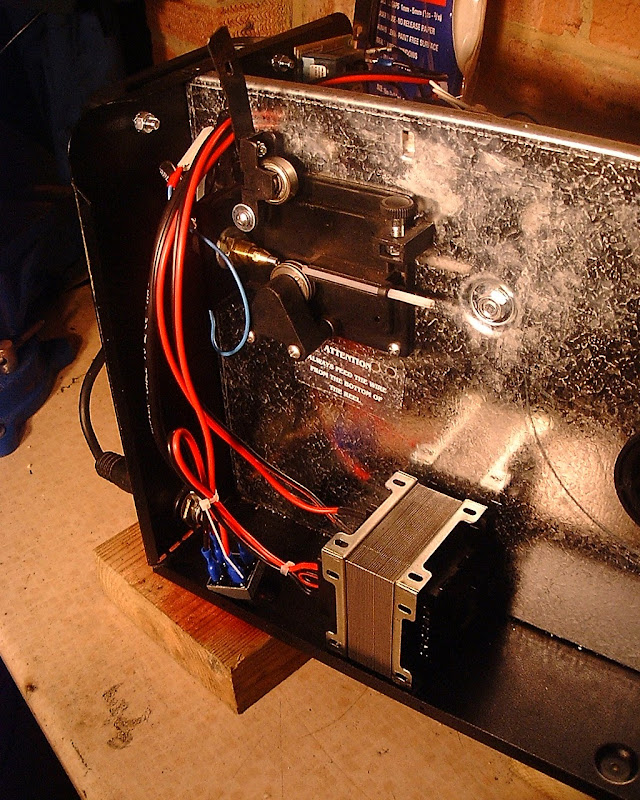
The first thing I had to do was find somewhere to put it, this proved some what difficult, as there is no space on the main transformer side in my machine (COSMO 150). After a swift cuppa I thought "Nuts to it" and cut a hole through the centre partition for the mains input side of the transformer to go, it looks a little like this.

OK, pretty it isn't. but I'm not really that fussed about the inside of a welder.
Also you can see where I've mounted the bridge, and the drive tie in place.
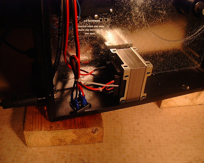
At this point I worked out where the transformer would sit and drilled the mounting holes for it as well as for the bridge, and just deburred them. placing the components roughly in position to gauge wire lengths.
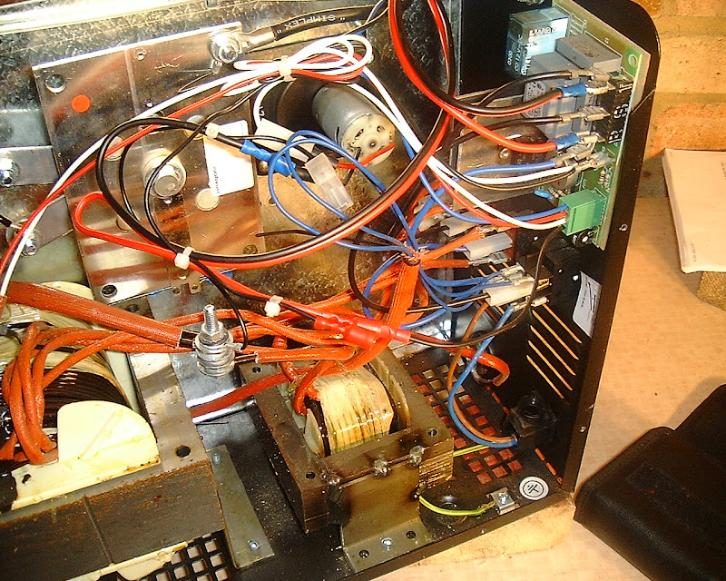
The next step was to start with the 240V side of the transformer. Using a multimeter to determine what was what the contacts highlight below are those that are switched by the contactor on the board.

By using piggy back terminals on these it makes it easy to revert if you wish to the initial setup, also saves on a bit of soldering.
these are the just connected to the 240V side of the transformer with the live feeding to 240, the neutral to 0 and the earth to the chassis earth of the welder, as seen below.

Next the 24V side was connected to the bridge (it is worth noting that this is a centre tap transformer that gives you +12V, 0V and -12V, by running from both +12v and -12V you get 24V), on the specified bridge the +ve is the pin that is in a vertical orientation with the -ve being diagonally opposite it. The AC flows into the bridge from the other two diagonally opposite terminals.

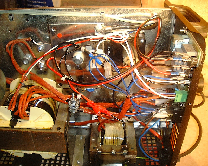
The output then passes thought the central partition to the motor feed and controller board.
The positive from the bridge connects to the black wire on the green box header on the board and the negative connects to the black wire on the motor.
as can bee seen in both images below.


all that is now left to do is to bolt down the transformer and bridge, then enjoy a much smoother feed!
I suggest adding the Metal tie as it also helps with the force on the wire.
Enjoy all!
EDIT> See also some thoughts about electrical safety for this mod
As requested here is a brief illustrated guide to adding an additional drive transformer.
For this you will need,
1 x ST100/240/24 transformer from Somer2000 Ask for Bob.
1 x AR84F from Maplin
2 x 1.5M lengths of 16Amp automotive cable (I went for red and black).
2 x Piggy back spade terminals
2 x spade terminals
2 x Insulated spade connectors
5 x M3 Bolts and nuts (Maplin again!!!)
Soldering Iron, solder and wire crimpers.
You will also need something to bludgeon your case, I initially used a drill and a jigsaw, before resorting to the grinder as my feet were getting cold.
**Disclaimer**
I do not condone plagiarism of any kind, the original idea came from AdrianH posted in this thread. The other modification is for the Tie between the drive rollers as performed by darrencambs here, this mod is noted as it appears in the images contained within.
The reason for adding an additional transformer is to stabilise the current to the drive motor. with the factory setup the drive motor draws it's current form the same transformer as the welding current, as a result as the torch moves closer and further away the current available to the drive system varies. This will also change depending on what power you have selected and even different diameters of wire.
So to help to circumvent this the addition of a dedicated drive transformer is an idea solution.
I performed some initial tests with an old laptop switching supply as a test method to see if it would help things out. The use of a switching supply is not recommended, as it will burn out fairly quickly and does tend to give run on.
For the transformer I chose to use I had a look around the net for a wirewound heavy duty unit, in the region of 20V at 3A (optimal for this application). This didn't really turn up much, however it did give me a good lead, Somer2000 have a transformer manufacturing division and are based just down the road from me at Radstock.
I gave them a call and laid out the problem to Bob, one of the directors. He came up with the idea of using a 24V 100VA unit, as this would provide a fairly close match and could be adjusted with the on board trim pot.
So for £35.25 (VAT & Delivery inc) this beastie arrived
Pint glass for size reference.
The first thing I had to do was find somewhere to put it, this proved some what difficult, as there is no space on the main transformer side in my machine (COSMO 150). After a swift cuppa I thought "Nuts to it" and cut a hole through the centre partition for the mains input side of the transformer to go, it looks a little like this.
OK, pretty it isn't. but I'm not really that fussed about the inside of a welder.
Also you can see where I've mounted the bridge, and the drive tie in place.
At this point I worked out where the transformer would sit and drilled the mounting holes for it as well as for the bridge, and just deburred them. placing the components roughly in position to gauge wire lengths.
The next step was to start with the 240V side of the transformer. Using a multimeter to determine what was what the contacts highlight below are those that are switched by the contactor on the board.
By using piggy back terminals on these it makes it easy to revert if you wish to the initial setup, also saves on a bit of soldering.
these are the just connected to the 240V side of the transformer with the live feeding to 240, the neutral to 0 and the earth to the chassis earth of the welder, as seen below.
Next the 24V side was connected to the bridge (it is worth noting that this is a centre tap transformer that gives you +12V, 0V and -12V, by running from both +12v and -12V you get 24V), on the specified bridge the +ve is the pin that is in a vertical orientation with the -ve being diagonally opposite it. The AC flows into the bridge from the other two diagonally opposite terminals.
The output then passes thought the central partition to the motor feed and controller board.
The positive from the bridge connects to the black wire on the green box header on the board and the negative connects to the black wire on the motor.
as can bee seen in both images below.
all that is now left to do is to bolt down the transformer and bridge, then enjoy a much smoother feed!
I suggest adding the Metal tie as it also helps with the force on the wire.
Enjoy all!
EDIT> See also some thoughts about electrical safety for this mod
Last edited by a moderator: