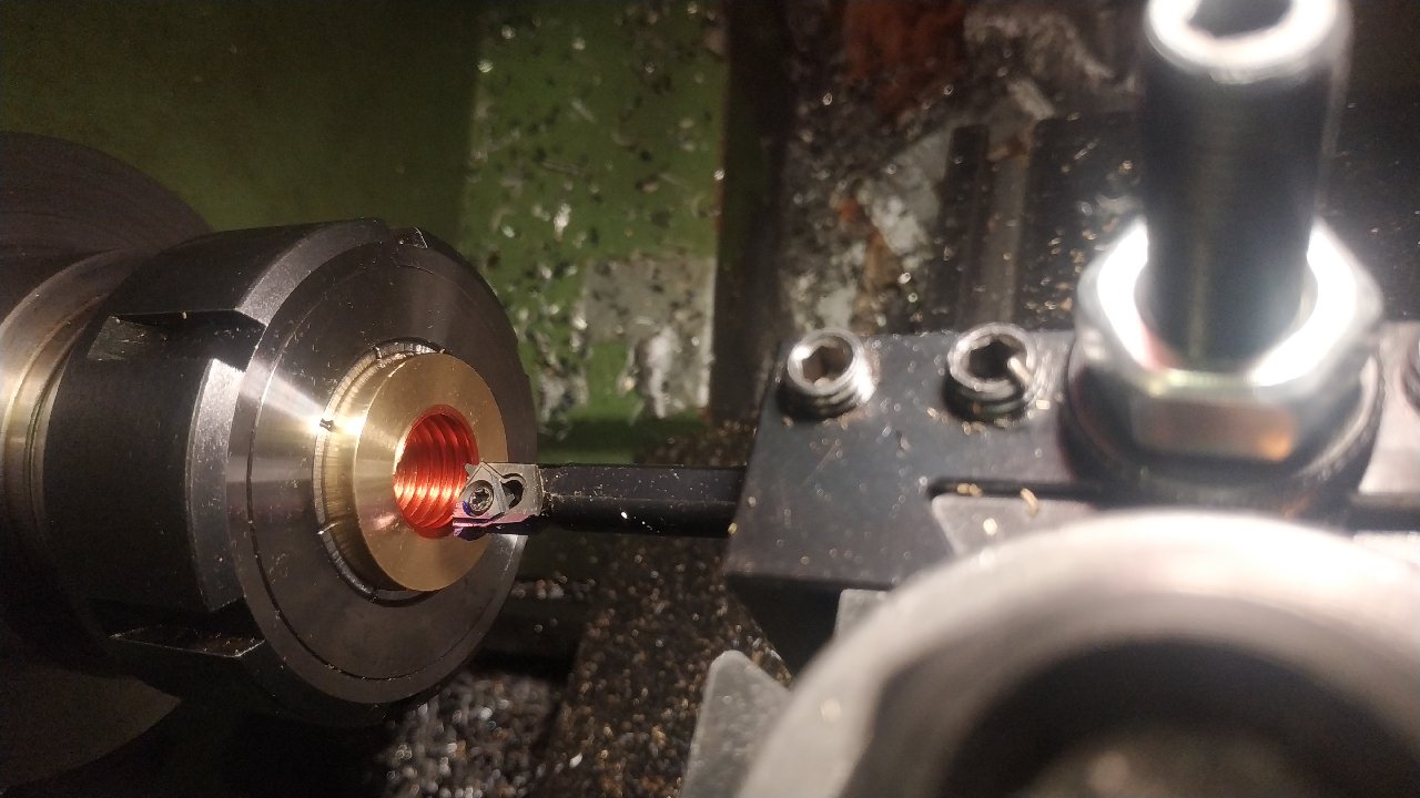
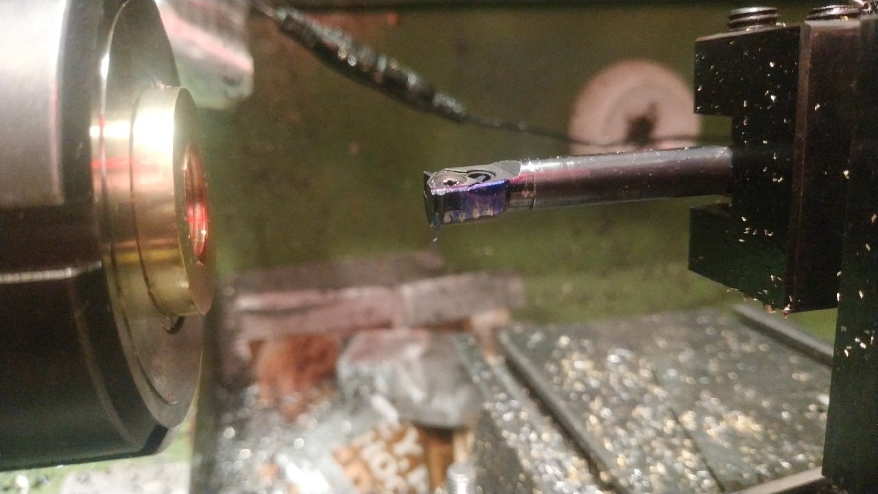
60 degree tool will remove more material than needed, thread will be weaker, but I am using high tensile Im sure it will be fine, I was just very unsure about the numbers above! Thread depth I was expecting 2.34 on my diamter dials (1.17). I calculated 21.03mm for a one wire using .98mm drill bit. Last cut got it to 21.01mm at 2.2mm depth on the dials, test fit screws on perfectly. 
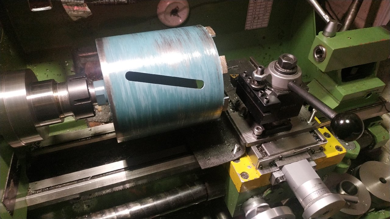
Took me all bloody day to make this adaptor, but for 5th threading attempt Im happy.
Well done. There's an immense satisfaction to be had that's for sure. Just watch out for raised burrs using that 1-wire method, it does rely on the OD remaining correct.
Fuuuu My gear popped out I was quick to stop the VFD and Ive lost about half a turn, so not ruined, its 40mm long anyway. My dial was at 2.2 out of 2.5mm depth for a 16mm 2TR nut, it is not quite done. Any one attempted to realign internal threads?
It is not easy but possible Run the lathe with the tool near the thread Stop the lathe and move the tool post until the tool is engaged in the thread If you are using insert tooling , I no longer use the compound reed for fine shallow threads just go straight in
As John said it's possible. Easier if you're not so close to the end but you have the advantage of a long thread. I use the compound to line it up. Run a black marker into the thread first a couple of times to lay a nice thick black coating on the thread. Get the half-nuts engaged and run the tool up to the thread then stop the motor and turn it in by hand about 1-2 turns in (so that the half-nuts are loaded in the cutting direction). Now use the compound to line it up somewhere near the middle of the thread. Wind out the cross slide until it's touching then back off about 0.2mm. Turn the chuck by hand and bring the tool out slowly until it scrapes one flank. Now take the lash out of the compound screw and zero the dial then use the compound to wind across until it's scraping the other flank. The middle of the cut is half the reading on the dial. That will get you close enough so it'll clean up both sides on subsequent passes.
Pick up the thread using the compound as the offset Just just make sure everything is in its driven position. Turn the spindle by hand
Very possibly, it is already mentioned in Joe's video above (he has also done one on picking up external threads), but another way is to leave the tool loose in the holder, engage it in the groove by sliding fore and aft (being angled, it self-centres) and then tighten the tool holder clamps. This works just as well for any angle your compound happens to be set.
Sounds not too bad I will try it. The important bit appears to be, to have the nuts and gears loaded in the cutting direction. I dont have the compound fitted, so I will use the loose tool and feel for the root of the thread. I dont understand why Joe used an indicator, as you say it will self centre at the bottom and be the same? Yes I know why the gear popped, bad design of the banjo. There is a coarse thread nut, but it will walk in or out if the washer rubs. Ive seen it bind before, so I added a spring on the top one, seemed to work, but clicks. I will do the same on the other.
If the compound is not fitted then I guess the loose tool method is the only choice. You're quite close to the finished size so if you get the assembly loaded in the right direction and line it up carefully it should work. Being trapezoidal just means you need a bit more care - a 60-degree thread would be a doddle.
Success! Thanks all for the help on this one! Lining it up was quick and seemed to be perfect, it was cutting on both sides. Progress was slow! I noticed this TR inserts are quite a bit deeper than most, meaning the boring bar overhangs the crest of the insert by a gnats nob. Few minutes with a needle file fixed, I thought! Bottom clearance, easily fixed. My dials were not accurate on this one, I think Ive taken off 2.8mm from the bore vs 2.5mm in machinery handbook. I am a little confused as it has two entries, ISO and DIN with different clearances at the root! Last pass wiped marker from crest of the insert and its a perfect fit so I am calling that done
Watched this and thought worth sharing. No idea what its for as the English captions are not available yet, but I want to copy it.
Wow, having watched that and seen the explanation of what the tools are doing at the end I understand how it was done I just don't want to think about the maths involved. And did you see the speed of that lead screw
I want to know how to set that up. Is he using the compound to do the multi start, plus alignment with all the tool changes? I notice he doesnt back out the cross when reversing. Is that a feature of the lathe?
It's an Archimedes screw for someone who only needs to raise water by about 6 inches.... OK, sorry... An impeller for a very special turbo??? Anyone's guess is as good as mine. Interesting use of a parting [style] blade abot 3 - 4 minutes in.
No, it's an indication of the wear in the leadscrew and halfnuts. You couldn't do it with normal threading because the form of the tool fills the space so the tool would catch the trailing thread flank before the leadscrew started pulling it back. His 'threads' have huge gaps between them so there's space for the tool to go into. It's a good visual example of why you must retract the tool between threading passes. An easy way to index the three starts is to un-bolt the chuck and move it around one bolt, if it has a 3-bolt fixing. Hard to tell if it's 3 or 4 bolts. Another way is to make it so that the lead of the part /3 is a multiple of the leadscrew pitch, then all you have to do is release the half nuts and move x number of threads and re-engage.