Good evening peeps, newbie to the site and yes you’ve guessed it “ Houston we have a problem “. I’ve had my welder for a good few years now and apart from replacing the torch and cable it’s been spot on. Then today midway through welding a panel it just stopped. The fan still runs but on pulling the trigger nothing , no gas , no click , no wire nada. Unfortunately I’m not that technically aufait it works or doesn’t ooops. So basically in layman’s terms I’m hoping that maybe some kind soul may be able to shed some light on the problem. Many thanks in advance
look at pcb board look for a box thats see through look to see if its dirty grey black sooty inside of it after that its a tester for you thats needed
Welcome! There's no external fuse access on these. Take the side panel off and you will likely find one, 1.5 amps, on an auxiliary transformer mounted to the case. If that has blown after replacement, my thread on this may help.
Thanks for the reply’s. I’ve taken the case off and taken a few pics but alas I can’t seem to find either the fuse or the see through box !! To my untrained eye nothing seems frazzled on the board or anywhere else.
I'd hang fire before doing that, as it'll cost you nearly £100. Although J2 on the pcb looks iffy?...or, it might be a RELAY. Can you post a general photo, showing everything inside?
getting old ones is hard so give a chance to find what you are after otherwise it was pointless theres many on the forum that might point you in the right direction try to get more of that pcb board into the picture it would help a little would also be prudent to also unscrew the pcb board and look for burnt out ints also look for dry joints on the board
Stand back a bit and take another? Trying to see if there a fused smaller aux transformer in there, fixed to the casing.....
Lol definitely needs a Hoover ay. There’s no fuse on the bit you mentioned though that I can see. I’ll just pop out to the garage and take a closer pic of the offending article
No fuse there. It's quite different to mine, which was 8 years older. Your pcb is surface mounted style, too. Just noticed all the steel grindings all over the motor ... definitely clean it out and check all the connections.
I guess that’s not good then , do you think this is the culprit then and not the board ? Is there a way of by passing it to confirm maybe ? Sorry but I really don’t know anything about them lol
I'm no expert on electronics but I manage to fix most transformer MIGs. Hopefully one of the real experts here will chime in soon! It's usually something basic, not the pcb, on most that I've fixed. Often it's just down to neglect. As a start, clean out all the crud, as conductive grinding dust could have caused a short. If you've replaced the torch before, check that's not got a connection problem. "J2" on the pcb looks like a relay. Does it look damaged, as I suggested? If so, that component can be replaced.
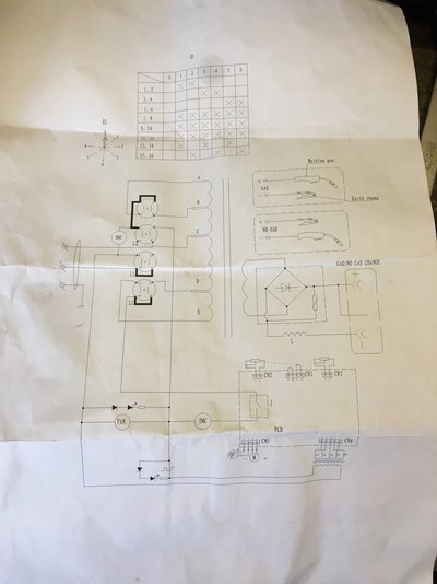
On the front panel there is an overtemperature LED, I think it is yellow. It will light when an overtemperature sensor opens, which will cut mains power to the primary of the "24v" auxiliary transformer. Is that LED on? For the next step, do you have a voltmeter? We need to check the auxiliary transformer. The quickest and safest way is to confirm that there is low-voltage AC ( 18v and 26v AC ) at the secondary. On the right-hand side of that transformer there are 4 red wires and one black wire. You need to set the meter to the 200v AC range and connect one meter probe to the black wire. The connections are well-insulated with yellow sleeving. If the meter probes have needle points you can pierce the sleeving, or maybe use pins. With the machine plugged in and the power switch on you should see 18v or 26v AC on the red wires ( no need to press the trigger switch ). The transformer secondary is low-voltage AC, it is not dangerous, but there are other components inside the welder where mains voltage is present, so only do this if you are confident of working on live equipment. I believe that this circuit diagram applies: