Post #8 of this thread has a circuit diagram: https://www.mig-welding.co.uk/forum/threads/sealey-170-1-voltage-control-switch.35966/
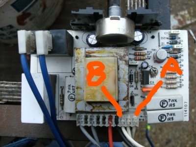
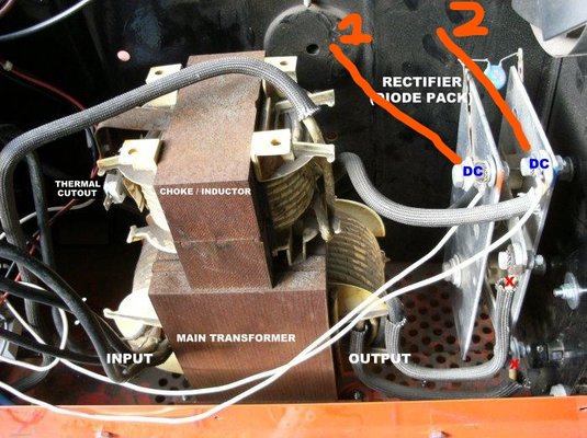
The wire with the fuse - "A" in your picture - goes to the negative of the rectifier. The negative plate of the rectifier is also bolted to the heavy wire from the inductor, so that is "2" in your picture.
For confirmation, the wire "B" in your picture goes to the positive of the rectifier, i.e. "1" , and that also has a thick black cable going to the MIG torch.