Nederlands
Member
- Messages
- 91
- Location
- Netherlands


Eddie49
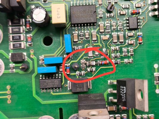
Unfortunatley you are right 4 off them seem to be broken
I did order a few extra so can replace them But have find out wat is causing them to burn
 www.manualslib.com
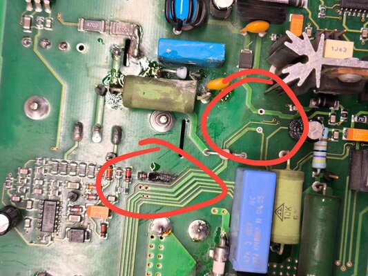
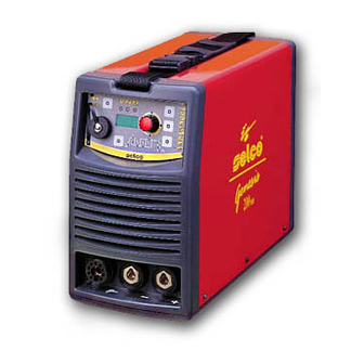
Hi. Can you help identify the resistors and the capacitor on the Selco Genesis 200 ACDC (almost the same as the Lincoln V205)?HI- WHAT PHOTO DO YOU NEED MAY BE I CAN END IT TO YOU LET ME KNOW OK THANKS
Hello, I am interested, I will buy all the tiles, contact me on whotapp no. 504797071 or at pietrwalski.przemyslaw@op.plwitam jestem zainteresowany ,kupie wszystkie płyteczki ,kontakt na whotapp nr.504797071
I'm interested in buying it because I can't handle my Selco. Please contact me.Thanx for the help everyone,
This is way harder than my knowledge allows
And would need extra tools to,
that i'm not able to handle correct.
So i decided to scrap it
And buy a new tig welder
Anyone interested in parts of this invertec?