


You are using an out of date browser. It may not display this or other websites correctly.
You should upgrade or use an alternative browser.
You should upgrade or use an alternative browser.
Poorly mig, can it live again??
- Thread starter flyingbenny
- Start date
Wedg1e
They call me Mr. Bodge-angles
- Messages
- 7,967
- Location
- Teesside, England
One little thing, the output rectifier is a full wave because the transformer is centre tapped - the output is just as smooth as using a bridge rectifier on a straight (non-tapped) transformer.
Oh for f**** sake, of course it is, sorry

 I'd amend the original post but too late now...
Anyone here know anything about electronics...?

flyingbenny
New Member
- Messages
- 16
- Location
- Mid Wales
Thanks guys
Wedg1e - that description is great, I'll read it a few more times and it should start to sink in, I'm getting the general gist of it but some still seems like scary black magic. I did notice One little thing, the output rectifier is a full wave because the transformer is centre tapped - the output is just as smooth as using a bridge rectifier on a straight (non-tapped) transformer but I think someone else already pointed that out!!!!!!!!!!!!!!!!!!!
Wallace - I did find that post after and my mate also confirmed it was a Nu-Tool (or Very Old-Tool now)
Going back to AdrianH's question a while back the white covered wire from the board seems to go direct to the transformer here:
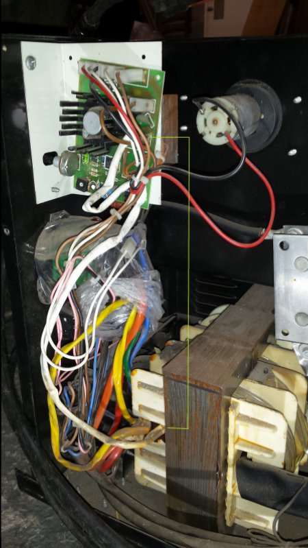
I have tried to do a wiring diagram if that would help?
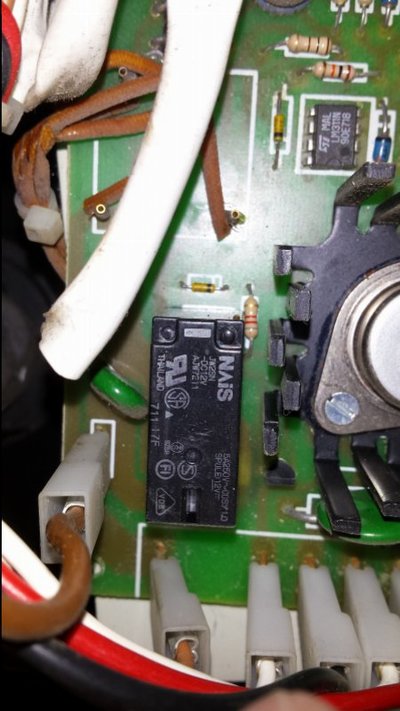
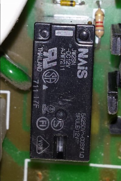
This is the relay behind which the board has burn out, am I likely to need to change this? If so what info do I need off it and is it the sort of thing I could get from Maplins (I'm afraid after Maplns I'm stumped when it comes to sourcing electronic wizardry components ).
).

What's the general consensus, do we think I (you) can get it going again or shall I condemn it to the skip???
There has been a slight turn up since starting this thread in that my boss has agreed to help me out with a new welder to replace this as I use it for the odd repair at work and it broke carrying out such a job. I would still like to get this up and running if at all possible just for the challenge but my next thread on here will be 'Which mig to buy under £400'.
Thanks again gents.
Ben
Wedg1e - that description is great, I'll read it a few more times and it should start to sink in, I'm getting the general gist of it but some still seems like scary black magic. I did notice One little thing, the output rectifier is a full wave because the transformer is centre tapped - the output is just as smooth as using a bridge rectifier on a straight (non-tapped) transformer but I think someone else already pointed that out!!!!!!!!!!!!!!!!!!!
Wallace - I did find that post after and my mate also confirmed it was a Nu-Tool (or Very Old-Tool now)
Going back to AdrianH's question a while back the white covered wire from the board seems to go direct to the transformer here:
I have tried to do a wiring diagram if that would help?
This is the relay behind which the board has burn out, am I likely to need to change this? If so what info do I need off it and is it the sort of thing I could get from Maplins (I'm afraid after Maplns I'm stumped when it comes to sourcing electronic wizardry components
).What's the general consensus, do we think I (you) can get it going again or shall I condemn it to the skip???
There has been a slight turn up since starting this thread in that my boss has agreed to help me out with a new welder to replace this as I use it for the odd repair at work and it broke carrying out such a job. I would still like to get this up and running if at all possible just for the challenge but my next thread on here will be 'Which mig to buy under £400'.
Thanks again gents.
Ben

Seadog
Save the planet. It's the only one with rum!
- Messages
- 13,232
- Location
- NE London - UK
I would still say the rectifier is short and there is a way to tell. BUT, it does mean the track needs repairing first, possibly a new relay as the points may be stuck, disconnecting one output from the transformer to rectifier and sticking a 24Volt headlight bulb in series (60 to 80 Watt). All of which means you have your hands inside the welder with it powered up and the trigger pressed.
To give yourself an idea of repair costs then have a look on Ebay for Welding rectifier and check the part number on the bit of paper on your rectifier and general layout and see if any similar and at what cost, I am assuming yours is a 170 Amp welder, but the way they are numbered it may well be less, you need to check the markings on the back for current settings.
The question is do you wish to do this or scrap it and buy another?
Adrian
flyingbenny
New Member
- Messages
- 16
- Location
- Mid Wales
Thanks for that, sorted.
I would still say the rectifier is short and there is a way to tell. BUT, it does mean the track needs repairing first, possibly a new relay as the points may be stuck, disconnecting one output from the transformer to rectifier and sticking a 24Volt headlight bulb in series (60 to 80 Watt). All of which means you have your hands inside the welder with it powered up and the trigger pressed.
To give yourself an idea of repair costs then have a look on Ebay for Welding rectifier and check the part number on the bit of paper on your rectifier and general layout and see if any similar and at what cost, I am assuming yours is a 170 Amp welder, but the way they are numbered it may well be less, you need to check the markings on the back for current settings.
The question is do you wish to do this or scrap it and buy another?
Adrian
I'll probably order a new mig anyway but i would still like to see if I can get this one going again.
I've ordered a relay so I'm going to have a go at soldering it in and repairing the track, would I be able to just bridge the gap with some wire or is that too agricultural, is there a better way? Once I've fitted the relay and done the track will it be ok to just press the trigger and see if it works? We'll see how that goes, if it's a success then perhaps I'll have a poke around inside with a bulb and check the rectifier.
On my rectifier it says PMS30 and MAGGIO 1998 which I'm assuming is the month and year. Now I've just done a quick search on PMS30 and this sealey rectifier came up http://www.ccw-tools.com/Sealey-120/112383---RECTIFIER-PMS-30__p-42972.aspx but it says it is out of a starter/charger, would this do? I can probably get a good deal on sealey spares, good enough to make it worth a gamble on and if it still doesn't work I won't have lost too much.
I got to borrow a Snap On 2180SX mig today to finish of my job, that was quite nice but he wouldn't let me keep it.
Cheers
Ben
flyingbenny
New Member
- Messages
- 16
- Location
- Mid Wales
The relay it self would not have caused the track to burn out, so my concern is that you replace the relay, wire the track and switch on and it just burns out again.
You have to find the fault on the set.
Adrian
Ok, I'll do the relay and the track, then I'll be back. Thanks for all your help.
Post a better picture of the rectifier, mark up all the wires where things go etc, then take it out, you should be able to test the unit off the welder to see if that has gone. It is in effect two diodes with the anodes together, (Generally around 4, 6 or 8 diodes), but you should never see a low resistance across the input of the rectifier, if one side of the bridge has gone short then current will pass one way, if both sides have gone short then it will be a short across the input side.
If you find/determine the rectifier is OK, then look for a bigger issue such as switch or transformer, in either case scrap.
Adrian
If you find/determine the rectifier is OK, then look for a bigger issue such as switch or transformer, in either case scrap.
Adrian
the snooper
getting older by the day
- Messages
- 21,063
- Location
- Hull UK
looking at the welder front panel it has a separate mains switch so power selector switch should be live only so no dead short therePost a better picture of the rectifier, mark up all the wires where things go etc, then take it out, you should be able to test the unit off the welder to see if that has gone. It is in effect two diodes with the anodes together, (Generally around 4, 6 or 8 diodes), but you should never see a low resistance across the input of the rectifier, if one side of the bridge has gone short then current will pass one way, if both sides have gone short then it will be a short across the input side.
If you find/determine the rectifier is OK, then look for a bigger issue such as switch or transformer, in either case scrap.
Adrian
flyingbenny
New Member
- Messages
- 16
- Location
- Mid Wales
Post a better picture of the rectifier, mark up all the wires where things go etc, then take it out, you should be able to test the unit off the welder to see if that has gone. It is in effect two diodes with the anodes together, (Generally around 4, 6 or 8 diodes), but you should never see a low resistance across the input of the rectifier, if one side of the bridge has gone short then current will pass one way, if both sides have gone short then it will be a short across the input side.
If you find/determine the rectifier is OK, then look for a bigger issue such as switch or transformer, in either case scrap.
Adrian
Will do boss!!!
The selector switches are typically on the mains side and the relay switches mains to the transformer, I am thinking 6 position multi-pole switch, that has three main connections and a low high as well, so position 1 is A & low, 2 is A & high, 3 is B & low, 4 is B & high, 5 is C & low and 6 is C & high. My old Cosmo 145 was like that. Or it could be multiple taps on one side, think I can see 6 coloured wires from the selector. The main difference here is the control board has no transformer so a bit like they use the rectified output to power the control board?looking at the welder front panel it has a separate mains switch so power selector switch should be live only so no dead short there
I would like to bet the control board is a re-worked one like this:-
http://www.eddiem.com/projects/mig/speedfix.html
It is all fixable.
Adrian
the snooper
getting older by the day
- Messages
- 21,063
- Location
- Hull UK
so your thinking the output from welding transformer / rectifier powers the pcb ?The selector switches are typically on the mains side and the relay switches mains to the transformer, I am thinking 6 position multi-pole switch, that has three main connections and a low high as well, so position 1 is A & low, 2 is A & high, 3 is B & low, 4 is B & high, 5 is C & low and 6 is C & high. My old Cosmo 145 was like that. Or it could be multiple taps on one side, think I can see 6 coloured wires from the selector. The main difference here is the control board has no transformer so a bit like they use the rectified output to power the control board?
I would like to bet the control board is a re-worked one like this:-
http://www.eddiem.com/projects/mig/speedfix.html
It is all fixable.
Adrian
I am not sure? I think this bit of the board (in yellow box) should normally have been a small transformer.
the bits in the red box are 4 diodes as a bridge rectifier for the likes of the speed control, in my mind at least as above it is the trim pot and the main wire feed control.

You would not want a mains driven speed control so can only assume it is fed back from the rectifier?
Adrian
the bits in the red box are 4 diodes as a bridge rectifier for the likes of the speed control, in my mind at least as above it is the trim pot and the main wire feed control.
You would not want a mains driven speed control so can only assume it is fed back from the rectifier?
Adrian
the snooper
getting older by the day
- Messages
- 21,063
- Location
- Hull UK
but it cant be fed from the welding rectifier as the welding transformer isn't energised until the relay is operated so it has to have an external power source to power the relayI am not sure? I think this bit of the board (in yellow box) should normally have been a small transformer.
the bits in the red box are 4 diodes as a bridge rectifier for the likes of the speed control, in my mind at least as above it is the trim pot and the main wire feed control.
View attachment 77651
You would not want a mains driven speed control so can only assume it is fed back from the rectifier?
Adrian
the snooper
getting older by the day
- Messages
- 21,063
- Location
- Hull UK
the make is nutool by the looks of itI have no idea what make it is
Ben
I know, that is what I finding hard to understand, that thin track you mentioned before on the board takes mains to a T1 pin then there are brown wires going off the board, and brown wires coming back on on where I would expect the secondary windings to be, wondering if there is another small transformer tucked away we have not seen, I notice there is signs of rework on the board already with an external resister and cut track?
Adrian
Adrian
the snooper
getting older by the day
- Messages
- 21,063
- Location
- Hull UK
I'm guessing a small transformer mounted somewhere, could also be part of previous repair, I cant find any nutool mig diagrams or any awelco which is I think the company that made themI know, that is what I finding hard to understand, that thin track you mentioned before on the board takes mains to a T1 pin then there are brown wires going off the board, and brown wires coming back on on where I would expect the secondary windings to be, wondering if there is another small transformer tucked away we have not seen, I notice there is signs of rework on the board already with an external resister and cut track?
Adrian


