You are using an out of date browser. It may not display this or other websites correctly.
You should upgrade or use an alternative browser.
You should upgrade or use an alternative browser.
NU-MIG135 Blows fuse when trigger is pressed.
- Thread starter bloobloo
- Start date
bloobloo
Professional Tinkerer
- Messages
- 271
- Location
- Ashton in Makerfield, Wigan UK
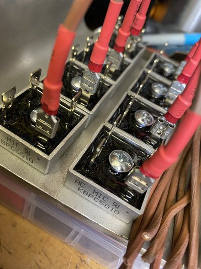
I have made the heatsink from 5" aluminium channel section, 8mm thick. I then marked, drilled and tapped the channel and bolted each diode to the channel. And that's as far as I got!All the bridge rectifier blocks should be mounted as close together as possible, on a heatsink thick enough to ensure that they are all at the same temperature.
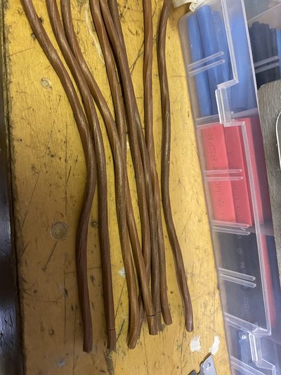
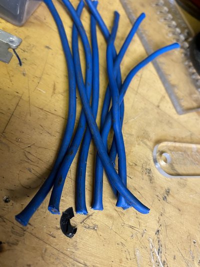
As long as they are adequately-sized for the expected current ( 5mm2 would be fine ), the leads do not have to be especially short, some resistance helps with current balancing. However, all the wires must be exactly the same length, so for 8 blocks you need to cut 32 identical pieces of wire.
One end of each group of 8 wires needs to be crimped and soldered to a common point - which can be flattened copper pipe. There will be four of these common points. If you have tight and well-crimped spade tags, they can be used to join to the rectifier tags. Otherwise, a fast soldered joint with a large temperature-controlled iron is preferable.
I am going to mount a pc cpu heatsink and fan onto the channel to help with cooling.
I will be cutting the cable today and crimping terminals onto one end for the diodes, the other ends will be soldered into 10mm pipe.
I will take some pics as I go and post them here, hopefully someone else can also gain knowledge and great help from this thread as I have.
This looks brilliant - going to have ago myself -Few pics for ya'll. Please excuse the mess
View attachment 297654 View attachment 297656 View attachment 297657
More pics tomorrow as things progress
View attachment 297654 View attachment 297656 View attachment 297657
Watching with interest
Few pics for ya'll. Please excuse the mess
More pics tomorrow as things progress
View attachment 297657
All those rectifiers for that diddly transformer

Surely not - you mean that having a constant reliable wire feed isn't as good as the auto-compensation system that the marketing department made such a big deal of...Bit off topic - but I’ve just tried a different psu for the wire feed and it’s like night and day on this machine

Haha - if only they would of spent a few extra quid on em - it was shocking before really bad - but was surprised how well it did .Surely not - you mean that having a constant reliable wire feed isn't as good as the auto-compensation system that the marketing department made such a big deal of...

bloobloo
Professional Tinkerer
- Messages
- 271
- Location
- Ashton in Makerfield, Wigan UK
You're right.......... I'll put some more in!All those rectifiers for that diddly transformer
You're right.......... I'll put some more in!

bloobloo
Professional Tinkerer
- Messages
- 271
- Location
- Ashton in Makerfield, Wigan UK
Speaking of soldering……
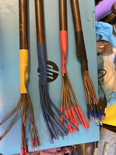
I made 4x 200mm lengths of 15mm copper pipe. 200mm is probably going to be too long, but it’s always best to cut off rather than add on. Then I need a way of securing 8 lengths of wire into it so that it is strong and secure. So big Chuck key and a vice! See pics as I’m sure they explain it better than me.
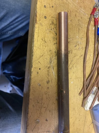
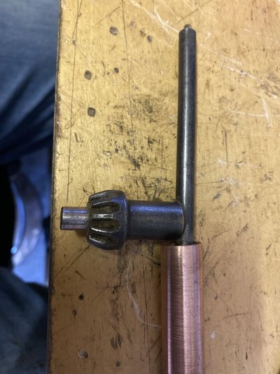
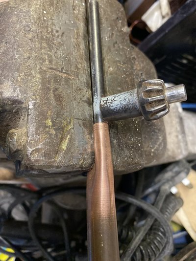
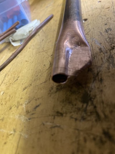
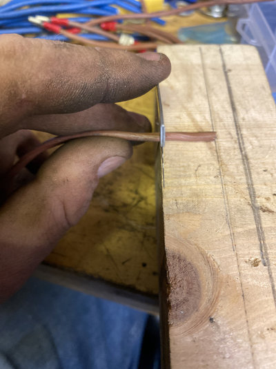
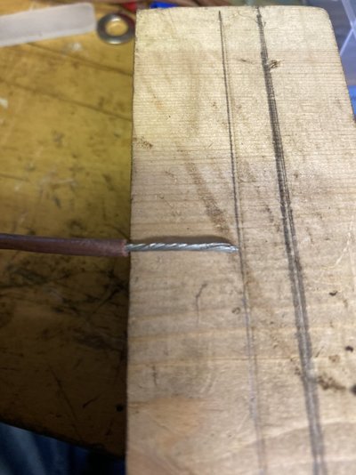
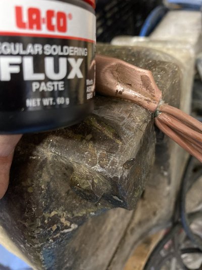
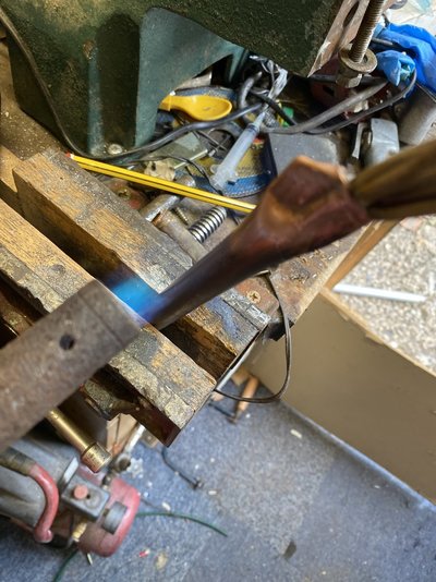
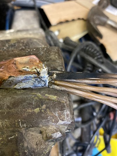
I made 4x 200mm lengths of 15mm copper pipe. 200mm is probably going to be too long, but it’s always best to cut off rather than add on. Then I need a way of securing 8 lengths of wire into it so that it is strong and secure. So big Chuck key and a vice! See pics as I’m sure they explain it better than me.


Typical Lancastrian - gives up as soon as there's a problemWell that didn't go well. Still tripping when trigger is pressed.
Very close to being launched into the canal.

I think you've been chasing two (or more faults). You've sorted one - the burnt out rectifier but not sorted out the other fault.
The welder has been seriously fiddled with and needs a bit more fettling to unfiddle it.
Going back a few steps.
Disconnect all the transformer's secondary wires from the rectifier. You should have four of them.
Connect the mains and turn the power on, then press the trigger. See if the fuse still blows. It shouldn't. If it does blow there is a wiring fault in the primary circuit. I don't think it will blow but let's wait and see.
If it doesn't blow the fuse (expected), turn the welder off, disconnect the mains plug then using your test meter se tto low Ohms range, identify the secondary windings, label them A0, A1 and B, B - as shown below.
Let me know how you get on and we can go to the next stage

D
bloobloo
Professional Tinkerer
- Messages
- 271
- Location
- Ashton in Makerfield, Wigan UK
Lancastrian... Sadly thanks to local gov't boundary changes I have to identufy as a "Greater Mancunian" or maybe a toaster or was it a tosser.... anyhow I digress.....Typical Lancastrian - gives up as soon as there's a problem
I think you've been chasing two (or more faults). You've sorted one - the burnt out rectifier but not sorted out the other fault.
The welder has been seriously fiddled with and needs a bit more fettling to unfiddle it.
Going back a few steps.
Disconnect all the transformer's secondary wires from the rectifier. You should have four of them.
Connect the mains and turn the power on, then press the trigger. See if the fuse still blows. It shouldn't. If it does blow there is a wiring fault in the primary circuit. I don't think it will blow but let's wait and see.
If it doesn't blow the fuse (expected), turn the welder off, disconnect the mains plug then using your test meter se tto low Ohms range, identify the secondary windings, label them A0, A1 and B, B - as shown below.
View attachment 297908
Let me know how you get on and we can go to the next stage
D
It has been fiddled with. Before it tripped, there was a spark from behind the circuit board. upon removing the board, it was clear that the soldered spikes on the reverse side had arc'd out on the chassis of the welder.
I have now placed a piece of acrylic between the board and the chassis to prevent this from happening again.
Just to be sure, I connected A0 and A1 to the positive side of the AC rectifier and B0 - B1 to the negative.
Is that right?
Lancastrian... Sadly thanks to local gov't boundary changes I have to identufy as a "Greater Mancunian" or maybe a toaster or was it a tosser.... anyhow I digress.....
It has been fiddled with. Before it tripped, there was a spark from behind the circuit board. upon removing the board, it was clear that the soldered spikes on the reverse side had arc'd out on the chassis of the welder.
I have now placed a piece of acrylic between the board and the chassis to prevent this from happening again.
Just to be sure, I connected A0 and A1 to the positive side of the AC rectifier and B0 - B1 to the negative.
Is that right?
Nope. It blew
Was that with the secondaries all disconnected and not touching each other ?
We typed that at the same time.
If the secondaries are totally disconnected, you have a fault in the primary circuit. This could be incorrectly wired to the switches when you put them back on or when you have disturbed the wires you have damaged the insulation and shorted the leads out.
Can you take a picture of the back of the switches and the transformer connections.


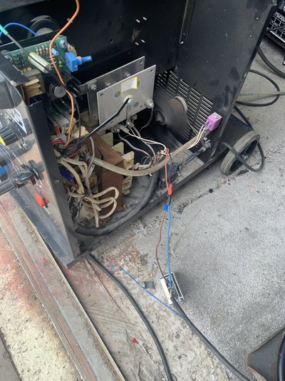
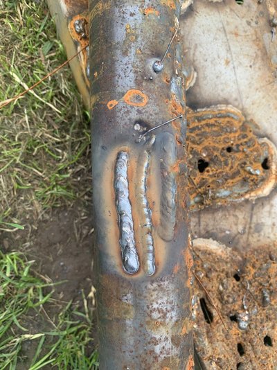
![IMG_1781[1].JPG IMG_1781[1].JPG](https://www.mig-welding.co.uk/forum/data/attachments/293/293962-4c6b025384a591bd34a724adf22311e6.jpg?hash=TGsCU4Slkb)
![IMG_1782[1].JPG IMG_1782[1].JPG](https://www.mig-welding.co.uk/forum/data/attachments/293/293964-fa92803254795727696acb58d537379c.jpg?hash=-pKAMlR5Vy)
![IMG_1784[1].JPG IMG_1784[1].JPG](https://www.mig-welding.co.uk/forum/data/attachments/293/293965-84cc08910b7697257a8c1a597a9951d0.jpg?hash=hMwIkQt2ly)
