I've got an adcock and shipley 1es production style machine.
When it was made, it only had a lead screw on the y-axis. Z was a lever feed and X was rack + pinion.
The X in particular made it a pain to use, as one turn on the wheel was roughly 4 inches of travel.
As a temporary bodge, I removed the rack+pinion bits and used a 16mm threaded rod for the x axis etc. This works OK, but it's tight to turn due to the bearings I used (bronze) - quick bodge, remember.
Anyway, now I want to improve the situation, so I've been looking at trapezoidal screws, which I'll likely go with, but the problem is that there's not a lot of space under the table for an x axis, so the bit where the table connects to the lead screw ends up hitting the carriage (I'm going to call this the "bearing block" going forward), if that makes sense.
The machine itself looks like this:
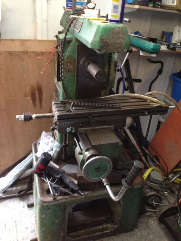
Basically, if the "bearing block" is too tall, it ends up hitting the sides, hence if I have bearings on both sides (screw in tension), and use a man sized screw, I end up with an x travel that is equal to the "overhang" bit in the picture above.
If I only support the screw on one side (left), I get a slightly longer travel, as the table can then move further towards the left.
What I want, however, is for the table to be able to move over to the right far enough that the spindle can mill all the way to the pocket in the table.
The only way I can think of doing this is to use a 12mm lead screw, as otherwise I don't think the bearings will fit.
The clearance between the table and the saddle is 35mm, and even that requires a bit of angle grinder action.
Now, if I mount the 12mm screw in tension, so to speak, do you think it will be strong enough? I note that the y-axis lead screw is about 20mm thick, but it's unsupported on one end, so presumably that means that it needs to be stout to stop it bending under cutting forces?
The machine is, and will remain, manual, but I'm hoping to be able to mill small steel parts with it at some point, to a reasonable accuracy (repeatable to 0.5mm if possible).
When it was made, it only had a lead screw on the y-axis. Z was a lever feed and X was rack + pinion.
The X in particular made it a pain to use, as one turn on the wheel was roughly 4 inches of travel.
As a temporary bodge, I removed the rack+pinion bits and used a 16mm threaded rod for the x axis etc. This works OK, but it's tight to turn due to the bearings I used (bronze) - quick bodge, remember.
Anyway, now I want to improve the situation, so I've been looking at trapezoidal screws, which I'll likely go with, but the problem is that there's not a lot of space under the table for an x axis, so the bit where the table connects to the lead screw ends up hitting the carriage (I'm going to call this the "bearing block" going forward), if that makes sense.
The machine itself looks like this:
Basically, if the "bearing block" is too tall, it ends up hitting the sides, hence if I have bearings on both sides (screw in tension), and use a man sized screw, I end up with an x travel that is equal to the "overhang" bit in the picture above.
If I only support the screw on one side (left), I get a slightly longer travel, as the table can then move further towards the left.
What I want, however, is for the table to be able to move over to the right far enough that the spindle can mill all the way to the pocket in the table.
The only way I can think of doing this is to use a 12mm lead screw, as otherwise I don't think the bearings will fit.
The clearance between the table and the saddle is 35mm, and even that requires a bit of angle grinder action.
Now, if I mount the 12mm screw in tension, so to speak, do you think it will be strong enough? I note that the y-axis lead screw is about 20mm thick, but it's unsupported on one end, so presumably that means that it needs to be stout to stop it bending under cutting forces?
The machine is, and will remain, manual, but I'm hoping to be able to mill small steel parts with it at some point, to a reasonable accuracy (repeatable to 0.5mm if possible).
")