mike 109444
Member
- Messages
- 4,879
Was typing a reply then realized I had typed the same in post 27! So....
The AUX transformer is the small transformer (looks about 6" square) just behind the yellow three terminal choc block where the L3,L2,L1 go in.
There is a thin blue wire (and possible black) on left side that looks to feed 24v ac? to the fan. It will have an input to it! (maybe 240V from one of the 3 phases). It may also have other outputs for the low AC voltage going to the bridge in the pcb box. You should find on the bridge there are two AC input terminals marked with "~" and a terminal marked "+" and one marked "-". If you meter the inputs you should have between 24 to 30 vAC. Then on the +&- outputs you should see a similar DC voltage. Unless these voltages are very much higher or LOWER then that part of the AUX transformer is ok.
Re check what's in the bold.
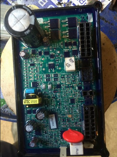
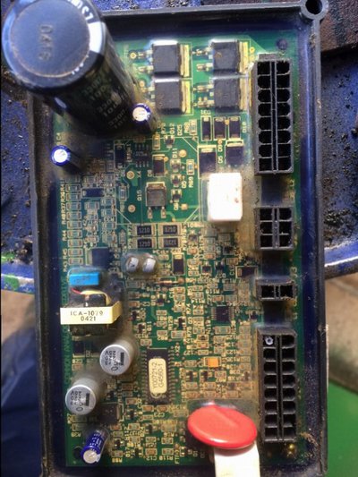
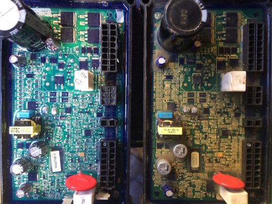
It's the Aux that provides the power to pcb
The AUX transformer is the small transformer (looks about 6" square) just behind the yellow three terminal choc block where the L3,L2,L1 go in.
There is a thin blue wire (and possible black) on left side that looks to feed 24v ac? to the fan. It will have an input to it! (maybe 240V from one of the 3 phases). It may also have other outputs for the low AC voltage going to the bridge in the pcb box. You should find on the bridge there are two AC input terminals marked with "~" and a terminal marked "+" and one marked "-". If you meter the inputs you should have between 24 to 30 vAC. Then on the +&- outputs you should see a similar DC voltage. Unless these voltages are very much higher or LOWER then that part of the AUX transformer is ok.
Re check what's in the bold.
It's the Aux that provides the power to pcb