mike 109444
Member
- Messages
- 4,879
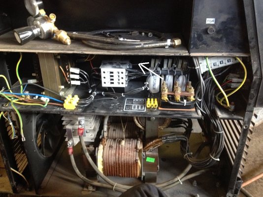
It does not look like there are any relays on the pcb so would suspect one of the four transistors at the bottom of the pcb ( the three legged devices) one may be shorted. If you have a meter it might be possible to compare each device by metering the three pins to see if there is one showing different than others.(assuming they are all the same, check any number on them).
If you switch welder on and it operates the contactor (you call the main switch/relay) if when you then pull the trigger does the wire THEN feed? and or GAS valve operate?
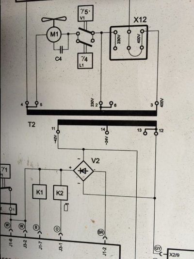
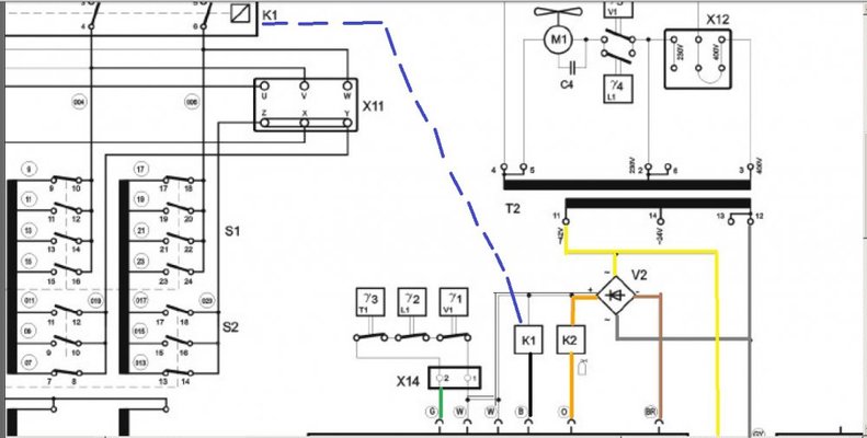
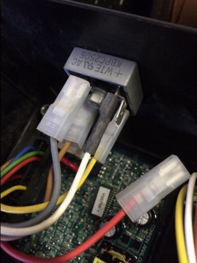
The reason disconnecting the wire from the rectifier stop it is because you have removed the low voltage supply to the pcb. Same I would suspect for the plug that you remove.
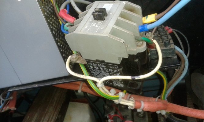
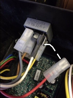
If you look at the contactor there will be two thin wires (rather than the thick wires on it) going to/from it, probable connected on it to something like A1 and A2.
This pair of wires should be the ones that feed a low voltage to the contactor to make it operate. You should follow these wires back to the pcb. Then that will show you where on the plugs it is getting it's feed from. Then you will have to see what connects on the pcb to that pair of wires. Then post a GOOD pic of the pcb indicating the wire pair.
If you switch welder on and it operates the contactor (you call the main switch/relay) if when you then pull the trigger does the wire THEN feed? and or GAS valve operate?
The reason disconnecting the wire from the rectifier stop it is because you have removed the low voltage supply to the pcb. Same I would suspect for the plug that you remove.
If you look at the contactor there will be two thin wires (rather than the thick wires on it) going to/from it, probable connected on it to something like A1 and A2.
This pair of wires should be the ones that feed a low voltage to the contactor to make it operate. You should follow these wires back to the pcb. Then that will show you where on the plugs it is getting it's feed from. Then you will have to see what connects on the pcb to that pair of wires. Then post a GOOD pic of the pcb indicating the wire pair.