You are using an out of date browser. It may not display this or other websites correctly.
You should upgrade or use an alternative browser.
You should upgrade or use an alternative browser.
Clarke 100EN - PCB
- Thread starter Ianh99
- Start date
I am not aware of a full circuit diagram for the E1289 PCB, only functional-level diagrams with the whole welder.
E.G. Page 27 here:
There is an annotated picture of that board from mike 109444 in this thread:
The 30v AC output of the small transformer on the board is half-wave-rectified by a diode and fed to the operating coil of the relay when the torch switch is closed at Pins 1 and 5. You could jumper across those pins to test, and trace the tracks from the transformer secondary to find the diode.
On the "EN" models the torch has two thin wires connected to the switch. [ Gas-only models have only one, and "borrow" the main DC power cable in the torch sleeve as the second switch conductor.]
The power transistor and the rest of the speed control circuit for the wirefeed motor is separate to the relay power-up circuit.
E.G. Page 27 here:
There is an annotated picture of that board from mike 109444 in this thread:
Afternoon all, I've been reading this forum for some time now picking up tips so firstly many thanks to all those that have heed without realisation over the years.
I've however got to the point that where I can't find the answer and need to ask the question.
My 135 was working fine until it stopped feeding, initially I thought it was the gun. Stripped and cleaned contact spring and block seemed to resolve. On the next welding run it died again, initially I thought it might have been duty cycle but after leaving there was still no joy.
Cover off and PCB inspection, all tracks look...
The 30v AC output of the small transformer on the board is half-wave-rectified by a diode and fed to the operating coil of the relay when the torch switch is closed at Pins 1 and 5. You could jumper across those pins to test, and trace the tracks from the transformer secondary to find the diode.
On the "EN" models the torch has two thin wires connected to the switch. [ Gas-only models have only one, and "borrow" the main DC power cable in the torch sleeve as the second switch conductor.]
The power transistor and the rest of the speed control circuit for the wirefeed motor is separate to the relay power-up circuit.
Thanks eddie49. I energised the relay today with a separate 20v supply, and it operated fine, so I know the relay itself is not at fault. I have tested across pins 1 and 5 as you suggest, and sure enough, I get a full short when the trigger is pulled, so no problems there. I have followed the tracks from the secondary winding and I think I have located the diode you suggest - tests fine.
This has me flummoxed!
I'm tempted to cut my losses and purchase a replacement board (available from Clarke), but I don't really want to admit defeat on what is a fairly straightforward circuit.
This has me flummoxed!
I'm tempted to cut my losses and purchase a replacement board (available from Clarke), but I don't really want to admit defeat on what is a fairly straightforward circuit.
I agree that it would be a shame to have to replace this board for a simple relay problem.
After half-wave rectification the 30v AC that you measured out of the transformer secondary will probably show as about 20 volts DC. This voltage should be present across Pins 1 and 5 when the welder is powered on. If you simulate the torch trigger by shorting across those two pins, the voltage between 1 and 5 will drop to zero. It has to go somewhere, and that is supposed to be the coil of the relay!
The most frequent fault on these PCBs is failure of the small potted transformer. It is usually the primary that burns out. This fault has been seen many times on this Forum. An intact primary has quite a high resistance - 1k or 2k Ohms, sometimes even just above 3k. The resistance of the secondary is typically a few hundred Ohms.
Perhaps your transformer can deliver the microAmps needed to indicate 30v AC on a digital meter, but not the milliAmps that the relay coil needs?
Last edited:
Itfluxmeoff
Member
- Messages
- 48
- Location
- Scotland
Whatever the issue is now it's sounding like it was self inflicted.
You never explained in detail what the original issue was or showed photos of your welds to help diagnose the problem(s) you were having and your first steps were disassembling the welder rather than troubleshoot materials/settings/technique...
On the basis you removed most of the PCB components to test are you certain every polarized component has been refitted correctly or not been mixed with a similar item?
I'm thinking reversed diodes/caps/transistors.
You're right Itfluxmeoff - in terms of self-infliction! A bit of an own-goal I'm afraid!
I had convinced myself that, since the break in the track here was so clean and precise, that it was there by design!
Not so of course. Restoring continuity has the machine feeding again.
Not had chance to try any test welds yet, but I am hoping that having gone through the machine quite meticulously, that it will operate as it should.
I owe you a bit of history too. I picked the machine up about two years ago (£20), with a dubious history, (previous owner mentioned something about the output transistor) despite being very clean and looking like it had had little use. On trying it, I found it fired up OK and I struggled forward with it on a variety of minor welding tasks - none of which I was particularly proud of, but put it down to my own inexperience.
It was only when - a few weeks ago - my son (who has an aging Cebora) had a go with it and said "this isn't right!" He couldnt maintain a decent bead regardless of settings.
As I said, I'll try some test welds and post them here!
I would just like to thank everyone for there input, and particularly those who have stuck with me through the diagnostic process! Much appreciated!
Itfluxmeoff
Member
- Messages
- 48
- Location
- Scotland
Having tried a variety of flux core wires I can assure you that a poor quality wire can make a huge difference so perhaps you were unlucky and you bought it with a roll of Super 6 installed.
When I was starting out I tried several rolls of it due to budgetary constraints and was convinced for a while that the machine at that time (90EN) was faulty.
Welds were inconsistent due to wire feed issues, the stuttering bead looking like bird crap after you wire brushed the flux residue and the spatter was extreme. I was ashamed to do small weld jobs for friends.
Don't get me wrong, the wire wasn't the only point of failure but it was the biggest factor. Having messed with hobby welders for a while now it's important to understand that the machine will usually require some fettling to work optimally, the wire feed design and finish of the plastics parts lets them down. Ensure the feed assembly is clean and all moving parts move freely-file plastic burrs/apply a smear of grease etc.
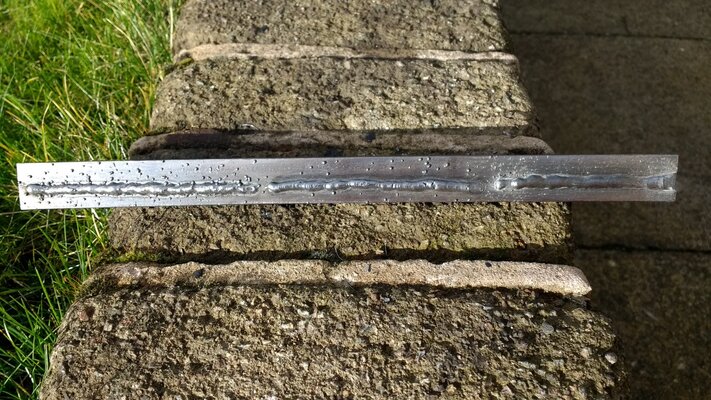
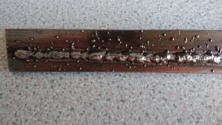
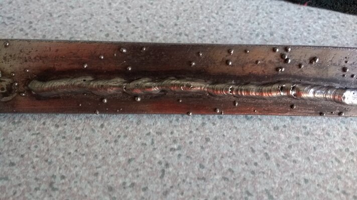
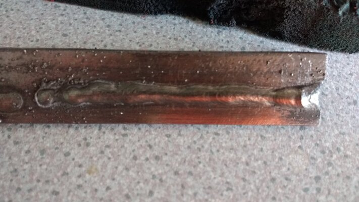
Just for a quick comparison here's an old test I did to show a friend on a scrap piece of 25x3mm angle. All beads were made with 0.9mm wire at 90A without changing feed speed. From left to right the wires are Super 6, Sealey, Parkside.
When I was starting out I tried several rolls of it due to budgetary constraints and was convinced for a while that the machine at that time (90EN) was faulty.
Welds were inconsistent due to wire feed issues, the stuttering bead looking like bird crap after you wire brushed the flux residue and the spatter was extreme. I was ashamed to do small weld jobs for friends.
Don't get me wrong, the wire wasn't the only point of failure but it was the biggest factor. Having messed with hobby welders for a while now it's important to understand that the machine will usually require some fettling to work optimally, the wire feed design and finish of the plastics parts lets them down. Ensure the feed assembly is clean and all moving parts move freely-file plastic burrs/apply a smear of grease etc.
Just for a quick comparison here's an old test I did to show a friend on a scrap piece of 25x3mm angle. All beads were made with 0.9mm wire at 90A without changing feed speed. From left to right the wires are Super 6, Sealey, Parkside.