


- Forums
- Tools, Compressors and Metal Coatings
- Tools, Materials and Techniques
- Machining
- Lathes and other Machining Equipment
You are using an out of date browser. It may not display this or other websites correctly.
You should upgrade or use an alternative browser.
You should upgrade or use an alternative browser.
M300 lathe wiring contactors and overload relay etc
- Thread starter M K
- Start date


- Messages
- 14,822
- Location
- UK
If you need any safety/limit switches let me know I have a bucket full of industrial osiswitches by telemechanique.
Thanks Pete. Subject to testing they all look to be present - its just the plumbing bit inbetween thats the taxing bit.
Thanks Milkybars. Pepper Road in Leeds is only a stones throw from us. Long, long gone now i guess. Love old stuff like this.
Milkybars
Member
- Messages
- 1,246
- Location
- Essex
@Welderpaul Hmmmm that one that was for sale on ebay in Leeds ..recently ??
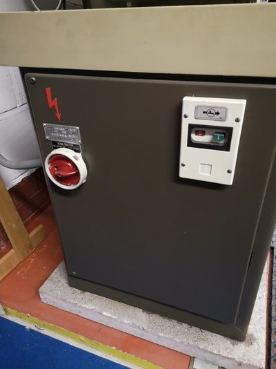
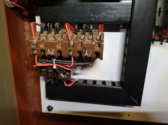
Please see more pics, hopefully this will make the schematic come to life
Please see more pics, hopefully this will make the schematic come to life
-
 IMG_20200331_205256.jpg166.1 KB · Views: 105
 -
 IMG_20200331_205531.jpg427.6 KB · Views: 90
 -
 IMG_20200331_205551.jpg325.1 KB · Views: 95
 -
 IMG_20200331_205607.jpg395.1 KB · Views: 97
 -
 IMG_20200331_205626.jpg176 KB · Views: 90
 -
 IMG_20200331_205652.jpg326.3 KB · Views: 91
 -
 IMG_20200331_205923.jpg245.6 KB · Views: 89
 -
 IMG_20200331_205931.jpg141.1 KB · Views: 90
Paul in Wiltshire
Member
- Messages
- 54
- Location
- UK Wiltshire
I pretty much started from scratch except for the existing limit / microswitches. The Harrison Group on groups.io has a file section that includes a typical diagram to set up for single phase, but it isn’t really that complex.
Here is my panel, I replaced the terminal blocks with some Weidmuler ones from RS. Schneider VFD from Inverter Supermarket. Old capacitor to provide pseudo three phase for coolant pump. 24 V contactor for emergency stop (along with a 24V power supply that provides power for the control circuits, and will power some LED lighting. I wanted the VFD in the panel, as once they are programmed there is no need to see them. To get it to fit I cut a section out of the panel and welded it so that I had somewhere to fix the VFD. You obviously need a VFD narrow enough to do this, as well as a VFD that doesn’t need side ventilation.

Original estop button replaced, and pot added to allow speed control of VFD. Pilot light replaced with a light/ momentary switch. The momentary switch is used to latch the contactor on to power the VFD. So if there is a power cut or you hit the estop, you have to press this button to re-energise the VFD. There is also some start protection built into the VFD. Foot brake switch is wired to the VFD to trigger a coast stop. If you hit the brake, you don’t want the VFD fighting the brake with a ramp down time.

Here is my panel, I replaced the terminal blocks with some Weidmuler ones from RS. Schneider VFD from Inverter Supermarket. Old capacitor to provide pseudo three phase for coolant pump. 24 V contactor for emergency stop (along with a 24V power supply that provides power for the control circuits, and will power some LED lighting. I wanted the VFD in the panel, as once they are programmed there is no need to see them. To get it to fit I cut a section out of the panel and welded it so that I had somewhere to fix the VFD. You obviously need a VFD narrow enough to do this, as well as a VFD that doesn’t need side ventilation.
Original estop button replaced, and pot added to allow speed control of VFD. Pilot light replaced with a light/ momentary switch. The momentary switch is used to latch the contactor on to power the VFD. So if there is a power cut or you hit the estop, you have to press this button to re-energise the VFD. There is also some start protection built into the VFD. Foot brake switch is wired to the VFD to trigger a coast stop. If you hit the brake, you don’t want the VFD fighting the brake with a ramp down time.
- Messages
- 14,822
- Location
- UK
http://myosuploads3.banggood.com/products/20190919/20190919015909SKU792664.pdf
Appreciate the posts and information fellas, some very impressive work! I like the idea of the VFD hidden away.
Not had a huge amount of time to fiddle with it, but here is a photo of the relevant page of the manual and the terminals available in the VFD.
Can i just run all the limit switch wires back to the VFD or do i need to do something a bit more taxing like Paul in Wiltshire or Milkybars has done?


I have a VFD on my M300 and have wired all the original switches through it tracing the wires is not hard the hard bit I found was working out how to get the VFD configured to work on the original switches
Appreciate the posts and information fellas, some very impressive work! I like the idea of the VFD hidden away.
Not had a huge amount of time to fiddle with it, but here is a photo of the relevant page of the manual and the terminals available in the VFD.
Can i just run all the limit switch wires back to the VFD or do i need to do something a bit more taxing like Paul in Wiltshire or Milkybars has done?
- Messages
- 14,822
- Location
- UK
I pretty much started from scratch except for the existing limit / microswitches. The Harrison Group on groups.io has a file section that includes a typical diagram to set up for single phase, but it isn’t really that complex.
Here is my panel, I replaced the terminal blocks with some Weidmuler ones from RS. Schneider VFD from Inverter Supermarket. Old capacitor to provide pseudo three phase for coolant pump. 24 V contactor for emergency stop (along with a 24V power supply that provides power for the control circuits, and will power some LED lighting. I wanted the VFD in the panel, as once they are programmed there is no need to see them. To get it to fit I cut a section out of the panel and welded it so that I had somewhere to fix the VFD. You obviously need a VFD narrow enough to do this, as well as a VFD that doesn’t need side ventilation.
View attachment 220135
Original estop button replaced, and pot added to allow speed control of VFD. Pilot light replaced with a light/ momentary switch. The momentary switch is used to latch the contactor on to power the VFD. So if there is a power cut or you hit the estop, you have to press this button to re-energise the VFD. There is also some start protection built into the VFD. Foot brake switch is wired to the VFD to trigger a coast stop. If you hit the brake, you don’t want the VFD fighting the brake with a ramp down time.
View attachment 220136
@Paul in Wiltshire did you reuse the existing (NVR?) suds pump switch when you rewired it?


