


You are using an out of date browser. It may not display this or other websites correctly.
You should upgrade or use an alternative browser.
You should upgrade or use an alternative browser.
Wire feed PSU mod - wire speed won't increment
- Thread starter skotl
- Start date
mike 109444
Member
- Messages
- 4,868
Do you have a circuit diagram for your welder ?
Gramas
Member
- Messages
- 77
- Location
- Northumberland
Don't have anything for itDo you have a circuit diagram for your welder ?
mike 109444
Member
- Messages
- 4,868
If you can take a pic of it's pcb and innards and post them on here could be it uses the same guts as many others of the SIP range.
Jim Davey
R H Davey Welding Supplies Ltd
- Messages
- 5,653
- Location
- Southampton
The meter needs a feed from welding circuit, you can pick up on the positive and negative outputs on the rectifier, or on the torch power connection at the drive plate for the positive and follow the earth back to its connector to find a negative.
I will say this isn't work that somebody who isn't electrically trained should be tackling though.
I will say this isn't work that somebody who isn't electrically trained should be tackling though.
Last edited:
Gramas
Member
- Messages
- 77
- Location
- Northumberland
Yeah I'm bit of a novice but if took pics and folk marked on where I'm fine with wiring etc just need picture guidance hahaThe meter needs a feed from welding circuit, you can pick up on the positive and negative outputs on the rectifier, or on the torch power connection at the drive plate for the positive and follow the earth back to its connector to find a negative.
I will say this isn't work that somebody who isn't electrically trained shouldn't be tackling though.
Other option is find shop in Newcastle to do all work but can't find any that service to public
Jim Davey
R H Davey Welding Supplies Ltd
- Messages
- 5,653
- Location
- Southampton
You have got the option to buy a better welding machine in the first place. Spending time, money and effort on trying to overcome the design flaws in an SIP 130 turbo seems a bit pointless to me when you could put the extra towards something that works better straight out of the box.
Gramas
Member
- Messages
- 77
- Location
- Northumberland
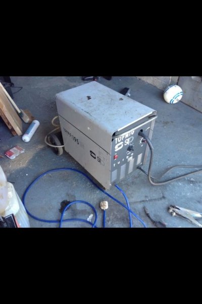
It's
It's a sip 195 just rather have it modded and cost me next to nothing too so shelling out £100 on mods ain't to bad and from what read it turns them into ok ish hobby welder
You have got the option to buy a better welding machine in the first place. Spending time, money and effort on trying to overcome the design flaws in an SIP 130 turbo seems a bit pointless to me when you could put the extra towards something that works better straight out of the box.
It's a sip 195 just rather have it modded and cost me next to nothing too so shelling out £100 on mods ain't to bad and from what read it turns them into ok ish hobby welder
mike 109444
Member
- Messages
- 4,868
You could simply take the metering from the two connections on the feed motor (noting Pos and Neg!) This will give a reading when the trigger is pulled, which is the case with most smaller welders as the voltage to the motor is only present when pulling the trigger. It would be more accurate than the marks on the dial for the wire feed though.
Gramas
Member
- Messages
- 77
- Location
- Northumberland
Thanks for reply that's a mod I can easily do as just basic wiringYou could simply take the metering from the two connections on the feed motor (noting Pos and Neg!) This will give a reading when the trigger is pulled, which is the case with most smaller welders as the voltage to the motor is only present when pulling the trigger. It would be more accurate than the marks on the dial for the wire feed though.
Jim Davey
R H Davey Welding Supplies Ltd
- Messages
- 5,653
- Location
- Southampton
There's an easier way to do that. You measure the wire feed speed at ten different settings on the dial and write them on a chart.
Take a watch and a tape measure and feed out wire at your first setting for ten seconds then stop and measure how much wire came out. Multiply the result by six an this will give you an accurate meter per minute rate.
You repeat the process at even steps all the way to max (often 1-10).
Going a stage further, if you fit a volt meter to the machine that shows welding voltage you can look up the matching mpm feed rate to volts to get a decent welding condition from the first pull of the trigger.
For instance, using Milker weld calculator at 17-18 volts, 6.3 mpm of 0.8mm mig wire should give a condition suitable for welding 2.0mm material.
Ok, you can arrive at these settings by trial and error, but that process can be short circuited by knowing what your machine puts out before you start welding.
Kram
Member
- Messages
- 8,659
- Location
- Sussex
Interesting thread, didnt realise the motor voltage would change with weld power settings, something Ill check on my Sealey. I like the idea about the panel volt/amp meters, Ive got a couple spare perfect for that.
Another option is put a optical wheel/rotary encoder on the motor shaft (or spool but the diameter changes) or use a stepper motor. Assuming no slip on the rollers, you will always get the same speed. There are cheap, off the shelf parts to do this.
Another option is put a optical wheel/rotary encoder on the motor shaft (or spool but the diameter changes) or use a stepper motor. Assuming no slip on the rollers, you will always get the same speed. There are cheap, off the shelf parts to do this.
skotl
Forum Supporter
- Messages
- 10,512
- Location
- Edinburgh, UK
Exactly.No to drive motor so get idea of settings inline with the feed dial helps in future to get same setting
Not sure where Jim is going but the wirefeed meter (Mike's idea) is to get a constant 0V and +V (anywhere up to ~30V) to power the meter, then the signal in (the voltage that it is measuring) is just the +ve feed to the wirefeed motor.
Nothing to do with the welding voltage.
Gramas
Member
- Messages
- 77
- Location
- Northumberland
Yeah that's what I want to do , seen post and thought great really would help find settings more accuratlyExactly.
Not sure where Jim is going but the wirefeed meter (Mike's idea) is to get a constant 0V and +V (anywhere up to ~30V) to power the meter, then the signal in (the voltage that it is measuring) is just the +ve feed to the wirefeed motor.
Nothing to do with the welding voltage.
Jim Davey
R H Davey Welding Supplies Ltd
- Messages
- 5,653
- Location
- Southampton
Sorry, my suggestion will work on any conventional MIG where wire feed speed isn't influenced by voltage step setting on the machine.
No good noting wire feed speeds throughout the range as they will change every time you alter volts.
What an awful idea.
No good noting wire feed speeds throughout the range as they will change every time you alter volts.
What an awful idea.
Gramas
Member
- Messages
- 77
- Location
- Northumberland
Ah right , baffled nowSorry, my suggestion will work on any conventional MIG where wire feed speed isn't influenced by voltage step setting on the machine.
No good noting wire feed speeds throughout the range as they will change every time you alter volts.
What an awful idea.


