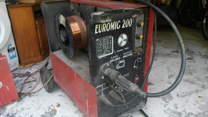
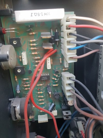
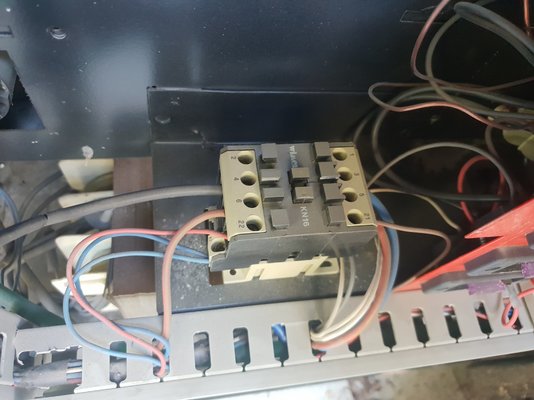
Don't have a diagram but I do have a working Euromig with the same PCB in it, should be able to get some voltage readings for the connections sometime if it's any help.
You may be able to get a rough idea of the voltage by checking the maximum working voltage marked on the electrolytic capacitors.
However, I do see 4 small diodes next to each other, beside the largest capacitor - maybe a bridge rectifier? So the supply could be AC, perhaps on the two orange wires, and about 20 VAC.
There is not much in the way of components on the board. I guess it provides a very basic speed control, plus a timer - perhaps for spot welds. The power semiconductors are small, and have no heatsinks, so could only safely drive a small motor. Rather than reverse-engineer this board, you could probably get a Chinese pulse-width-modulated ( PWM ) 40 Amp motor speed controller for 20 AUD.
I used one of those Chinese PWM boards in a SIP and it seemed to work pretty well.
As for this board struggling to figure it out.
Top set of connectors blue and red give 40vdc with red +. Black in top set goes to feed motor with red at feed motor constant +.
Lower 4 black and brown wires seem to be 20vac between black and brown
Red and blue are connected to this box which has 240vac going into the other side....
wacky7791, the box is the contactor ( heavy duty relay - Wimex KN16 ), which powers the main welding transformer on/off when pressing the trigger on the torch. The spot weld timer on the board can control the ON time of that contactor.
Your board is slightly different in that instead of the four small diodes, it really does have a bridge rectifier ( the round black component marked with + - ~ ~ ), so now I'm sure that the power supply into the board is AC.
Yeah noticed the bridge rectifier in place of the diodes, used to replace them on dyson washing machines, common failure of them.
Looks like you were right on the 20vac input of the 4 lower wires too, hadn't notice your comment on that earlier and that's what mine read as. Feed motor recieves a constant 40vdc positive and the board looks to control the negative?
I might give up on this board then seeing as though it is able to only drive a small motor. I know the motor that came off it looked like it came out of a toy remote control car, maybe slightly larger.
I have a 24V gear motor that I would like to use, similar type to a wiper motor.
If I go with the eBay PWM type board how would I go about controlling the contactor and gas solenoid and also burn back control? Timers would be good as well but they would probably over complicate things.
I would start by measuring the current that your 24v motor draws, with a moderate load, from 2 x 12v car batteries. Then obtain a suitable mains-to-24v DC power supply, with a couple of amps extra capability.
In the most basic circuit, this auxiliary power supply will be "on" as soon as you power up the welder. Via the MIG torch trigger switch, it will send 24v to the gas solenoid, the eBay wire feed motor PWM board, and the contactor for the main welding power source. However, that contactor may have a coil voltage that is not 24v - e.g. it could be 240 v AC - in which case you would need to drive the contactor through the contacts of a small slave relay with a 24v coil.
You may also not want all these current loads running off the microswitch in the MIG torch handle - so that means you start with a multi-pole relay off the trigger.
I'm not sure if a simple Chinese PWM board will power up, feed the wire at the pre-selected speed, then stop and brake the motor ( to prevent over-run ) just by applying and then cutting off the input power. Braking is normally by disconnecting the power source and shorting the motor. Your geared motor may have enough drag to solve that.
Once you mention burnback, it gets more complicated - and more interesting! To get burnback, the welding power contactor has to stay engaged for a time ( preferably variable ) after the wire feed ( and gas ? ) stop. That means a timer for the main contactor, triggered by the "off" ( low-going ) signal. Once you start getting into timers, you may as well go the whole hog and add variable spot-weld and stitch-weld timers....! Limited by my 1970s electronics experience, I would have to cobble all this functionality together by using 74-series TTL logic, 74123 monostables, and NE555 timers. Those with more recent skills will tell you that you could easily do this with a microcontroller, or an Arduino, or a Raspberry PI, plus a mere 5,000 lines of C code....