Shox Dr
Chief Engineer to Carlos Fandango
- Messages
- 17,868
- Location
- East Yorkshire
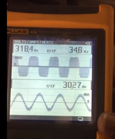
Cant remember where this came from or out of what. I ‘found’ it again today while looking for something else.
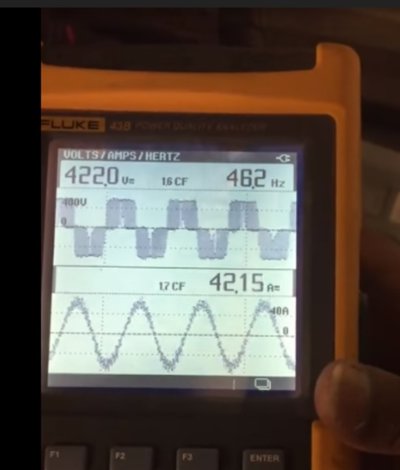
Looks to me its 415 in 400/380 plus neutral and 200v
All 3ph


Its a fair lump weighing 17kg. No data plate.
Looks to me its 415 in 400/380 plus neutral and 200v
All 3ph
Its a fair lump weighing 17kg. No data plate.