


You are using an out of date browser. It may not display this or other websites correctly.
You should upgrade or use an alternative browser.
You should upgrade or use an alternative browser.
Transformer help needed
- Thread starter jordan1
- Start date
GrahamGKD
Forum Supporter
- Messages
- 1,422
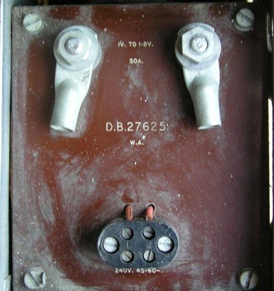
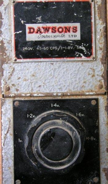
Looks to me like you connect your mains to the lower terminals (where it says 240v) and that your lower voltage output (selectable via the rotary switch) is connected to the upper terminals (where it says 1 to 1.8v). The size of cables will depend on how much current you plan to draw - i.e. how heavy is the load?
Graham
Graham
Looks to me like you connect your mains to the lower terminals (where it says 240v) and that your lower voltage output (selectable via the rotary switch) is connected to the upper terminals (where it says 1 to 1.8v). The size of cables will depend on how much current you plan to draw - i.e. how heavy is the load?
Graham
Hi Graham, that much I had deduced but the wires are not colour coded, so which is which, the available loads are shown in the pic. Need a sparky on this one, thanks anyway.
rtbcomp
Moderator
- Messages
- 18,575
- Location
- Sheffield UK
You don't need colour codes, connect live & neutral to the lower terminals, either way round, and I'd also connect the earth wire to one of the screws, the bottom LH one seems to have a tag there already.
Again if the output is AC you connect those terminals to the AC connections on your rectifier, either way round, it doesn't matter.
For the full 50 amps you'd be looking at 6mm^2 cable.
Again if the output is AC you connect those terminals to the AC connections on your rectifier, either way round, it doesn't matter.
For the full 50 amps you'd be looking at 6mm^2 cable.
You don't need colour codes, connect live & neutral to the lower terminals, either way round, and I'd also connect the earth wire to one of the screws, the bottom LH one seems to have a tag there already.
Again if the output is AC you connect those terminals to the AC connections on your rectifier, either way round, it doesn't matter.
For the full 50 amps you'd be looking at 6mm^2 cable.
You're to the rescue once again, very much appreciated.
")
You don't need colour codes, connect live & neutral to the lower terminals, either way round, and I'd also connect the earth wire to one of the screws, the bottom LH one seems to have a tag there already.
Again if the output is AC you connect those terminals to the AC connections on your rectifier, either way round, it doesn't matter.
For the full 50 amps you'd be looking at 6mm^2 cable.
Just looking at my plating book, it specifies + to anode and - to diode so how do I ID the output cables?.
Cheers
rtbcomp
Moderator
- Messages
- 18,575
- Location
- Sheffield UK
If it's just a transformer the output will be AC so you will need to wire a rectifier in the circuit to convert the AC to DC.
If it has a rectifier built in then use a digital voltmeter to identify the terminals. With the meter set to 10v DC connect it to the output terminals, if you get a positive reading the + meter lead will be connected to positive, if you get a negative reading the + meter lead will be connected to -ve.
If it has a rectifier built in then use a digital voltmeter to identify the terminals. With the meter set to 10v DC connect it to the output terminals, if you get a positive reading the + meter lead will be connected to positive, if you get a negative reading the + meter lead will be connected to -ve.
GrahamGKD
Forum Supporter
- Messages
- 1,422
Hi Graham, that much I had deduced but the wires are not colour coded, so which is which, the available loads are shown in the pic. Need a sparky on this one, thanks anyway.
I'm not a sparkey but I do have a degree for electronic engineering in a drawer somewhere - long time ago mind you! Sorry if I misunderstood your question. Graham.
If the output of the transformer is AC you will need a fairly big power diode or rectifier to handle the current. You should find a nice big stud mounting rectifier on ebay though. Would be a good idea to have an ammeter to read the current too, an automotive will be easily available, just ensure the scale reads at least 60 amps.
shenion
Tool Pack Rat
- Messages
- 7,586
- Location
- Stone Mountain, GA USA
If it is AC and only 1-1.8V, then adding a diode will drop about 0.7v and only give half wave out. A full wave bridge will drop 1.4V so near nothing left either way.
you will nee Shotkey diodes that are a bit better with 0.5V drop
you will nee Shotkey diodes that are a bit better with 0.5V drop
Need a sparky on this one, thanks anyway.
Worrying!
Worrying!
?? confused:
rtbcomp
Moderator
- Messages
- 18,575
- Location
- Sheffield UK
If it is AC and only 1-1.8V, then adding a diode will drop about 0.7v and only give half wave out. A full wave bridge will drop 1.4V so near nothing left either way.
you will nee Shotkey diodes that are a bit better with 0.5V drop
I would guess the voltage indicated will be RMS, the peak will be RMS x 1.4 which will be present at the output of the rectifier, so 1.4 to 2.5 volts, before allowing for the voltage lost accross the diode(s).
I've got an idea this may have been intended for use with copper oxide rectifiers. They had a very low peak inverse voltage, low forward voltage drop, but could handle high currents. For most things they became obsolete years ago, but they were still used in electro-plating.
The rectifier may be internal. You should be able to tell whether the output is AC or DC (and if so which way round) with a meter.
There just maybe people who still make copper oxide rectifiers for electroplating.
The rectifier may be internal. You should be able to tell whether the output is AC or DC (and if so which way round) with a meter.
There just maybe people who still make copper oxide rectifiers for electroplating.
