- Forums
- Tools, Compressors and Metal Coatings
- Tools, Materials and Techniques
- Machining
- Lathes and other Machining Equipment
You are using an out of date browser. It may not display this or other websites correctly.
You should upgrade or use an alternative browser.
You should upgrade or use an alternative browser.
Tom Senior Light Vertical arrived!
- Thread starter Guineafowl
- Start date
Guineafowl
Member
- Messages
- 1,440
- Location
- Nairn
Nothing special, just remove motor and top cover, drive pulley, then four bolts to remove the motor mount housing. The spindle is fine so I left it at that. The play in the spines is no big deal, just a light knocking when doing interrupted cuts eg fly cutting.Id be interested to see how the head was striped.
Guineafowl
Member
- Messages
- 1,440
- Location
- Nairn
I had some thoughts about the backlash in the X and Y directions. The screws are more worn in the middle, and I guess there’s some wear in the feed nuts as well. There’s a company in the US (Roton) that supplies Acme LH 5 tpi threaded rod for only about £12 per foot. With this, and a suitable LH thread tap, could I not make up some new feed screws/nuts?
Agroshield
Member
- Messages
- 6,230
...and a suitable LH thread tap...
Be wary of thinking in terms of 'a' tap. ACME is a difficult thread to tap. You might need a series of taps or a very long one with a very shallow taper on it. Do some research on what is available - if the US leadscrew is $100 but the tap(s) for the nut is/are $400, it is less attractive as an option.
Does the Roton rod have a spec. sheet showing its accuracy? ACME can be used for non-precision purposes (e.g. scissor jack screws) as well as for leadscrews so check it is the good stuff before you spend any money.
Depending on your preferences, it might be more practical to convert to metric. If the leadscrew and nut are available in metric as a standard item, you might get away with using the same dials (I am guessing that for 5tpi, they have 200 divisions so a 5mm pitch screw would play nicely with that number).
If you say the machine has been used for a lot of drilling, then it will have been going clockwise. If you turn the disassembled female spline part upside down on the male part, does it feel any tighter? If it improves things, is there a way of making that inversion a permanent fixture?
Is there a way to reconfigure the drive so that when you are flycutting, the spines are not used? Somehow (temporarily) lock the pulley and shaft together. You would lose the up and down of the quill but that might not matter.
Guineafowl
Member
- Messages
- 1,440
- Location
- Nairn
Interesting stuff, thanks. I guess the other answer is a DRO.
Regards tapping, I could partially cut the thread, then finish with the tap, which is also available from same company, as are bronze nuts that could be turned into sleeve inserts. I’ll ask about spec sheets.
The splines seemed to have lots of play either way around. Again, not a big deal, and the 3ph motor/VFD have improved things a lot (smoother power and soft start).
Shox Dr
Chief Engineer to Carlos Fandango
- Messages
- 17,866
- Location
- East Yorkshire
Ballscrew with an antibacklash nut would be cheaper. Ive started the ballscrew holders for both X and Y travel.I had some thoughts about the backlash in the X and Y directions. The screws are more worn in the middle, and I guess there’s some wear in the feed nuts as well. There’s a company in the US (Roton) that supplies Acme LH 5 tpi threaded rod for only about £12 per foot. With this, and a suitable LH thread tap, could I not make up some new feed screws/nuts?

Guineafowl
Member
- Messages
- 1,440
- Location
- Nairn
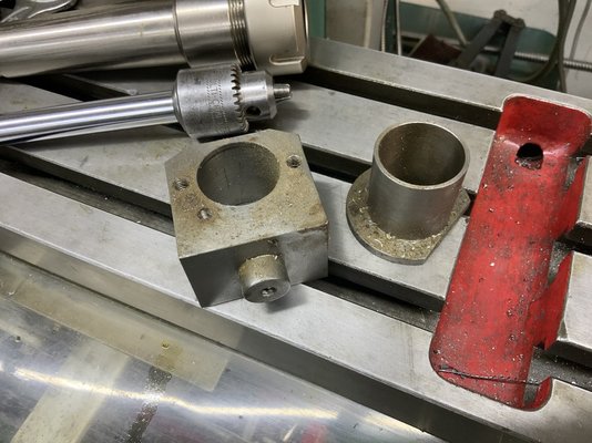
| Currently building up a mill control box (rev-off-fwd, e-stop, power and fault lights, rpm meter, speed pot) from an adaptable box and bits. Since the new motor shaft is only 40mm long, and the mount adapter is 10mm thick, I’ve only got a small amount of shaft inside the pulley, which is leading to vibrations if the belt is set to normal tightness. I’ve left it loose for now. The motor shaft has a 6mm thread in the end. Would it be feasible to turn a shaft extension of 19mm diameter, with a similar thread inside, and lock the two together with a length of 6mm studding? Also, I need to mount the RPM sender somehow. Reading a plastic disc, with magnet embedded, mounted on top of the spindle pulley seems feasible. Any other suggestions? |
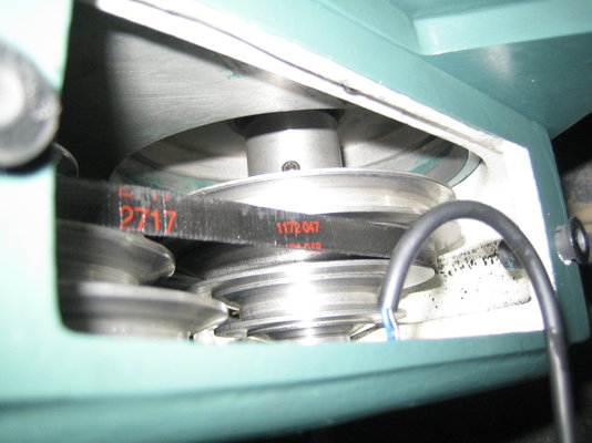
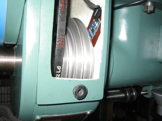
My motor pulley has an extension to the motor shaft (as part of the pulley). I mounted my tacho magnet in the bottom of the front pulley, the pickup is mounted on the bottom plate, wire comes out of the side cover.
I'll take some photos tomorrow, but it will probably be in the afternoon.
I'll take some photos tomorrow, but it will probably be in the afternoon.
Guineafowl
Member
- Messages
- 1,440
- Location
- Nairn
Thanks, I have the same pulley, but my motor is spaced away 10mm further by the ally adapter plate (new B14 -> old B56).
My RPM sender is oriented the other way (like a crank sensor) so might have to stick out the top.
My RPM sender is oriented the other way (like a crank sensor) so might have to stick out the top.
Tony Brazier
New Member
- Messages
- 12
- Location
- Herne Bay
Hi I brought some Roton Lead screw and it works great. Made a anti -blash nut from a couple of Roton nuts and it works great.
Guineafowl
Member
- Messages
- 1,440
- Location
- Nairn
I did email them, but got no response. Will try again. Do you have a link to what you bought?Hi I brought some Roton Lead screw and it works great. Made a anti -blash nut from a couple of Roton nuts and it works great.
Guineafowl
Member
- Messages
- 1,440
- Location
- Nairn
Modifications so far:
- 3ph 750W motor + VFD to replace the old 250W single phase one.
- Mill control box with RPM meter made up from bits. Might have been cheaper to get a ready-made one.
- Quick release Bristol lever for belt changes.
- Bronze thumb nuts for quill depth stop.
- Swarf bellows
- Made a machinist’s hammer (filled with lead shot), fly cutter and slitting saw arbour (not shown).
- Made some bastard 17mm AF x BSW nuts for the vice clamps and X axis stops, so I can use the same spanner as the drawbar.
- Made some ball-ended stalks for the cone clutches that engage the quill on either side. Used annealed ball bearings.
Tony Brazier
New Member
- Messages
- 12
- Location
- Herne Bay
Sorry no link, long time ago, the cost of delivery was more than the leadscrews.
Tony Brazier
New Member
- Messages
- 12
- Location
- Herne Bay
I remember just went found in catalogue and ordered with a couple of spare nuts to make my own anti-backlash nut. Will photo if picture required as not happy with Tom Senior nut location.
Guineafowl
Member
- Messages
- 1,440
- Location
- Nairn
Yes please. Pics always handy.I remember just went found in catalogue and ordered with a couple of spare nuts to make my own anti-backlash nut. Will photo if picture required as not happy with Tom Senior nut location.
Yes - I should have mentioned the next job is to mount the VFD inside the column, now I no longer need the front controls and to see the screen. Once I’ve found suitable glands to bring the cables in, that’ll be done.The VFD should be in an enclosure fixed in position. You will invariably have live contacts which could be touched either by hand or by small tool, etc.,
The minimum insulation requirement is two layers of insulation over/around any conductor at voltages exceeding about 50 volts, unless mounted inside an enclosure which requires either a safety interlock, or tools for opening said enclosure.
Guineafowl
Member
- Messages
- 1,440
- Location
- Nairn
Fitting a DRO
(https://www.ebay.co.uk/itm/36347079...NokiYnkOtOa2PA%3D%3D|ampid:PL_CLK|clp:2047675)
at the moment. I thought the Y axis would be the easiest, so started with that, but it turned out to be a bit faffy. Took ages, so I fitted the monitor, plugged in and played with the functions to give myself some motivation to fit the X and Z tomorrow.
I like the X stops and locking handle on the front, so was going to fit the X scale on the back of the bed. The vice sticks out the back anyway, so I won’t lose any more Y travel. Can you fit the X scale either way round (flipping horizontally, I mean)?


