Guineafowl
Member
- Messages
- 1,557
- Location
- Nairn
This puts out 12V, about 50W to power a mini-fridge, Peltier element I think:

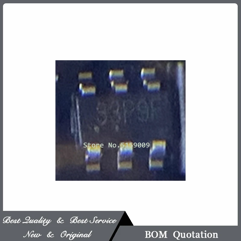
Some faulty components already removed, including bulged output caps, some shorted diodes, and blown chopper MOSFET. Unfortunately, the SOT23 switching controller has also shorted, and the closest replacement doesn’t quite match:

The OSC (frequency set) and CS (current sense) pins are transposed. I’m ok with swapping those around on the board, but in the old chip, the CS wasn’t used. Also, the new chip suggests a 95k resistor for the OSC leg, to set the switching frequency at 70 kHz. I’ll have to change the 271 currently there.
1. There is a 0.36ohm, 2w, gold band resistor on the Source of the chopper MOSFET, clearly intended for current sensing, even though it’s not used in this application. Would you leave the CS pin unconnected for the new chip, or hook it to the resistor as intended?
2. I can’t find out the operating frequency of the old chip, set by its 271 resistor. Would you replace with the 95k from the new chip’s datasheet?
3. Any other pitfalls? I’ll have to hope the existing optocoupler arrangement will set the correct output voltage.
Some faulty components already removed, including bulged output caps, some shorted diodes, and blown chopper MOSFET. Unfortunately, the SOT23 switching controller has also shorted, and the closest replacement doesn’t quite match:
The OSC (frequency set) and CS (current sense) pins are transposed. I’m ok with swapping those around on the board, but in the old chip, the CS wasn’t used. Also, the new chip suggests a 95k resistor for the OSC leg, to set the switching frequency at 70 kHz. I’ll have to change the 271 currently there.
1. There is a 0.36ohm, 2w, gold band resistor on the Source of the chopper MOSFET, clearly intended for current sensing, even though it’s not used in this application. Would you leave the CS pin unconnected for the new chip, or hook it to the resistor as intended?
2. I can’t find out the operating frequency of the old chip, set by its 271 resistor. Would you replace with the 95k from the new chip’s datasheet?
3. Any other pitfalls? I’ll have to hope the existing optocoupler arrangement will set the correct output voltage.