


You are using an out of date browser. It may not display this or other websites correctly.
You should upgrade or use an alternative browser.
You should upgrade or use an alternative browser.
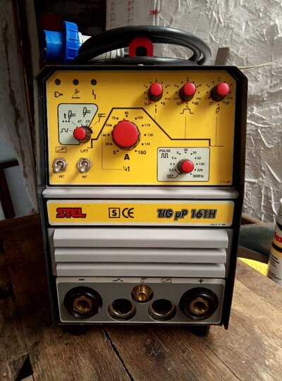
Stel Tig uP 161H DC - HF Electrode Cleaning & Setting
- Thread starter RichKem
- Start date


pedrobedro
Man at Matalan
- Messages
- 13,116
- Location
- CX near Chesterfield
I have a 201 tigup that hasn't been used for a few years, I'll have a look inside it one day.

Buonasera. Mi scuso per il mio inglese scarso (By google translate). Sono nuovo di questo forum e mi sono iscritto per ricevere supporto per la mia saldatrice Stel Tig uP 161h.
L'ho acquistato da un altro produttore di saldatrici impegnato in spionaggio industriale e l'ho rivenduto nel 2022.
Il mio problema deriva da un'esplosione degli IGBT nel circuito di potenza primario nel 2023, che sono stati poi sostituiti con altri con caratteristiche simili. La settimana scorsa si è ripetuto e sono davvero dispiaciuto. Vi chiedo, visto che vedo che molti di voi hanno lo stesso modello, se avete mai avuto lo stesso problema. Qualcuno potrebbe essere così gentile da aiutarmi con le foto dei circuiti che avete in casa, così posso confrontarli con i miei e capire se sono state realizzate versioni diverse o se il mio presenta difetti di fabbricazione?
Apprezzerei il vostro aiuto perché, come molti di voi, sono un hobbista e per me acquistare una nuova saldatrice è praticamente impossibile.
Grazie.
Translation of Post #5:
"Good evening. I apologize for my poor English (by Google Translate). I'm new to this forum and signed up to receive support for my Stel Tig uP 161h welder.
I purchased it from another welding machine manufacturer engaged in industrial espionage and resold it in 2022.
My problem stems from an explosion of the IGBTs in the primary power circuit in 2023, which were then replaced with others with similar characteristics. It happened again last week, and I'm truly sorry. Since I see many of you have the same model, I'm wondering if you've ever had the same problem. Could someone please help me with photos of the circuits you have at home, so I can compare them with mine and determine if different versions were made or if mine has manufacturing defects?
I'd appreciate your help because, like many of you, I'm a hobbyist, and buying a new welder is practically impossible for me."
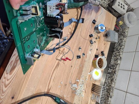
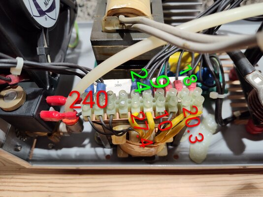
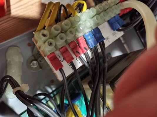
And the dramatic caption to the photo in Post #6:
"My welder and the bloodbath of the unsoldered power components"
"Good evening. I apologize for my poor English (by Google Translate). I'm new to this forum and signed up to receive support for my Stel Tig uP 161h welder.
I purchased it from another welding machine manufacturer engaged in industrial espionage and resold it in 2022.
My problem stems from an explosion of the IGBTs in the primary power circuit in 2023, which were then replaced with others with similar characteristics. It happened again last week, and I'm truly sorry. Since I see many of you have the same model, I'm wondering if you've ever had the same problem. Could someone please help me with photos of the circuits you have at home, so I can compare them with mine and determine if different versions were made or if mine has manufacturing defects?
I'd appreciate your help because, like many of you, I'm a hobbyist, and buying a new welder is practically impossible for me."
And the dramatic caption to the photo in Post #6:
"My welder and the bloodbath of the unsoldered power components"
Buonasera e benvenuti al Forum!
My reply would be that explosions of IGBTs in inverter welders are not so unusual, and do not imply that the machine had/has a manufacturing defect. The Italian company Stel is a good brand and their machines are far more reliable than cheap imported products, but failures will still happen.
My reply would be that explosions of IGBTs in inverter welders are not so unusual, and do not imply that the machine had/has a manufacturing defect. The Italian company Stel is a good brand and their machines are far more reliable than cheap imported products, but failures will still happen.
Thanks for your reply.
I think I realized that when translating the page into Italian, despite having entered the text translated by Google, the automatic translation of the page translated it back into Italian before posting the message on the forum.
I apologize.
So, in your opinion, is the explosion of IGBTs normal even with hobbyist use? Have you also had to replace these components multiple times?
Trying to understand the reasons, I appreciated the first post with the HF electrode gap because mine were 0.6 mm, so I corrected that as well.
I'm not an electrical engineer, but I realized that perhaps I made a mistake in 2023.
The Stel uP 161h used Infeon IRG4PC40U IGBTs (no longer in production because they are obsolete). I consulted a local shop and they recommended replacing them with Infeon IKW20N60T ones.
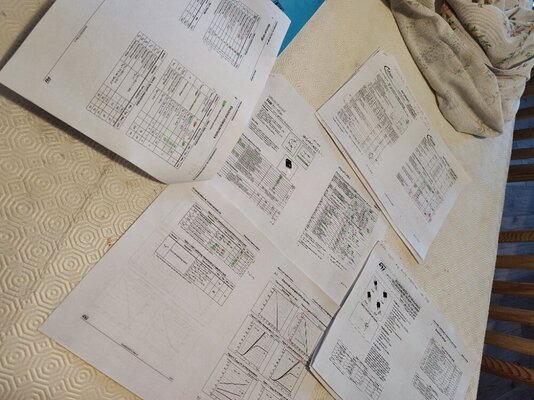
Last week, when they exploded again, I looked up their specifications, printed out the respective datasheets, and highlighted the various parameters with green and red highlighter. It turned out they had identical or slightly negligible parameters, except for the pulsed collector current (Icp) parameter. The native IGBTs have a value of 160 A, while the latter have a value of only 60 A.
Studying the parameter in question, I discovered it's the one that manages the current absorption peaks. So perhaps this is the reason for my second explosion.
I then searched for an IGBT with all the similar parameters, including the Icp parameter. I found the STGW40H60DLFB with identical parameters, except that it can operate at double the normal current (Ic continuous collector current at Tc=25°C, 80 Amp instead of 40 Amp), and Ic at Tc=100°C, 40 A instead of 20 A. I then asked an electrician if there were any problems using these "super-equipped" IGBTs, but he replied that in theory they're an improvement since they'll operate with currents lower than their maximum design current. I realized that this component works like a hydraulic solenoid valve that opens the current flow, modulating it based on the upstream circuit requesting it based on the control panel settings.
I'm ordering these components and hope to have no more problems, because the tracks are suffering greatly from repeated repairs.
I think I realized that when translating the page into Italian, despite having entered the text translated by Google, the automatic translation of the page translated it back into Italian before posting the message on the forum.
I apologize.
So, in your opinion, is the explosion of IGBTs normal even with hobbyist use? Have you also had to replace these components multiple times?
Trying to understand the reasons, I appreciated the first post with the HF electrode gap because mine were 0.6 mm, so I corrected that as well.
I'm not an electrical engineer, but I realized that perhaps I made a mistake in 2023.
The Stel uP 161h used Infeon IRG4PC40U IGBTs (no longer in production because they are obsolete). I consulted a local shop and they recommended replacing them with Infeon IKW20N60T ones.
Last week, when they exploded again, I looked up their specifications, printed out the respective datasheets, and highlighted the various parameters with green and red highlighter. It turned out they had identical or slightly negligible parameters, except for the pulsed collector current (Icp) parameter. The native IGBTs have a value of 160 A, while the latter have a value of only 60 A.
Studying the parameter in question, I discovered it's the one that manages the current absorption peaks. So perhaps this is the reason for my second explosion.
I then searched for an IGBT with all the similar parameters, including the Icp parameter. I found the STGW40H60DLFB with identical parameters, except that it can operate at double the normal current (Ic continuous collector current at Tc=25°C, 80 Amp instead of 40 Amp), and Ic at Tc=100°C, 40 A instead of 20 A. I then asked an electrician if there were any problems using these "super-equipped" IGBTs, but he replied that in theory they're an improvement since they'll operate with currents lower than their maximum design current. I realized that this component works like a hydraulic solenoid valve that opens the current flow, modulating it based on the upstream circuit requesting it based on the control panel settings.
I'm ordering these components and hope to have no more problems, because the tracks are suffering greatly from repeated repairs.
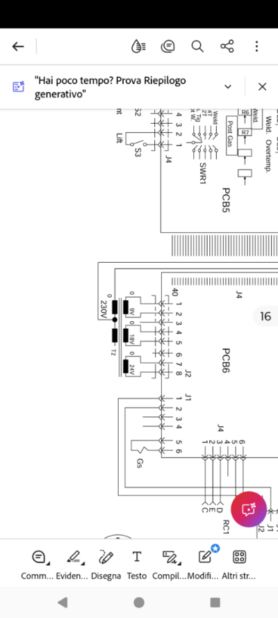
Continuing with the checks, I looked at the transformer output voltage next to the gas solenoid valve and the secondary PCB and the voltages read were a few volts higher. In your opinion, are they within tolerance or are they excessive enough to modify the operating currents that power the front control panel and consequently skew the final output voltages? Sorry for the thousand questions.
The tolerance for low AC voltages that are output from the secondary of a transformer is generally quite large. On the PCB there will be bridge rectifiers, smoothing capacitors, and possibly voltage regulators, and these components will affect the final DC supply voltages. I do not think that the AC voltage disparities that you have measured will have any effect.


