If anyone has got any ideas why my trusty Murex Tradesmig 135 has stopped working I would really appreciate it. I've had this machine for years, bought it second hand and not used it in a while. Everything seemed fine, got gas and wire feed, can hear the relay kicking in on trigger but I get a spark but no ARC. I thought it might be the earth, so I tried another lead but the same. I opened up the cabinet to look for loose/dirty joints, went all through them making sure they were tight, the capacitors look ok to me so I have run out of ideas. Any thoughts or suggestions gratefully received.
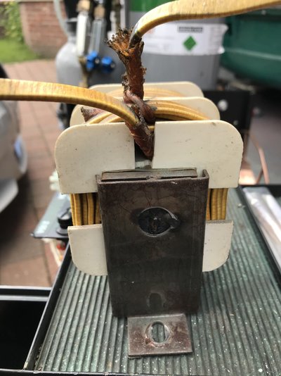
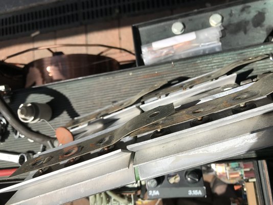
Having just posted and looked more closely at the pictures, can anyone tell me in the fourth picture the "windings" that look a bit like a transformer to me, that goes to the Earth clamp, in the centre of the bracket where the hole is looks like burning - is that normal? should it look like that? I will have a closer look at it tomorror.
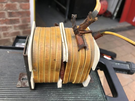
What high-quality photographs, and what an amazingly clean machine! The interior looks like it came out of the factory yesterday. Have you tried it on all positions of the power range switch? The relay that you can hear on pressing the trigger - is that the small one in a clear plastic case on the PCB, or the loud "clunk" of the Contactor ( the black device to the right of the capacitor bank ) ? With power on, you can simulate the torch trigger being pressed by carefully ( e.g. with an insulated screwdriver ) pushing in the manual operation button in the centre of the Contactor. Take care, live mains in that area !! With the button held in, try to get an arc. The wound component on the floor of the machine to the right of the main transformer is the inductor, or "choke". The thick flat copper strip windings carry the full welding current, back via the welding return cable ( the "Earth" cable ). The mounting bracket is welded to the laminations with a partial plug weld at the hole, and that is OK. However, the copper strip does look a little burnt or corroded at the insulating sleeve where it leaves the winding and heads to the front panel. Try gently scraping and bending the copper strip at that point, to check that it is still solid.
I'd check rectifier first, I've seen few of murex 135 with failed rectifier. Unless you find some dodgy connection
Thanks Stanbester - I had a good look at the rectifier and made sure all the connections were sound, but I dont really know how to check the rectifier - what would this involve?
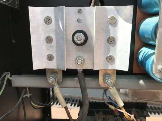
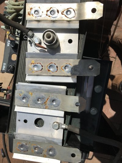
I held the button in on the contactor but still no Arc. I took out the Inductor to have a better look and it all seems sound, it was the plug weld as said by eddie49, and the copper strips are all solid. The rectifier has 12 diodes and visually they all seem ok. I have uploaded some detailed photos.
So I think I might have tested the rectifier, following guidance from other posts, I dont know if the attached photograph shows the results clearly enough, but the Rectifier is in two plates and I used a multimeter (I think!!) on the Diode/continuity setting and got these results either nothing or reversing the leads a value of between 437 & 448. The back half that goes to the top of the capacitor block was positive lead on the diodes, negative on the cable - left bank of 3 from the top 437,437,437 - Right bank 448,448,448 The front half that goes to the bottom of the capacitor block that goes to the inductor/choke then earth lead was negative lead on the diodes and positive on the cable - left bank of 3 from the top 446,447,447 - Right bank 438,438,438 I'm not an electrician as you might have guessed, so I really dont know if that makes any sense at all or if it is a valid test, but my guess is that the rectifier shows no visual signs and tests ok, if I have done it right. There is a little brown "resistor" with no markings that I couldn't get any reading from, not even any continuity. Let me know if I've made a hash of this or whether you can make any sense of it for me. Thanks for your help.
You've tested the four arms of what is a bridge rectifier. In your case each arm has 3 diodes in parallel, so your set of three readings for each plate is just the reading for one set of diodes (not sure what the erroneous 446 is for the left set). They look fine but, just for completeness, reverse the polarity and test again. There should be no noticeable reading
Thanks Seadog, when I reversed the leads, each time, there was no reading - is that the same as reversing the polarity? The erroneous 446 reading might just have been how the meter settled. So does that mean that the bridge rectifier on my Murex 135 is working correctly? If so what else might I look for?
Yes, reversing the leads is the correct procedure. The diodes look to be fine. When they fail, they fail, so even a low current test such as this will show any faults.
That was brave of you to dismantle the recifier! As Seadog says, it looks like the diodes are all OK. I would suggest checking the DC voltage from the torch tip to the return clamp ( "Earth" ), with the trigger pressed. At the lowest power setting this should be about 14v, rising to maybe 30v at the top setting. If that voltage is not OK, check the AC output from the main transformer. With your meter on the AC voltage range, look for about 15v AC to 30v AC across the two bolted connections at the bottom of the rectifier, where the thick copper strip come out from the secondary winding on the main transformer. The rectifier output will be DC, and that feeds in to the capacitor bank. The connections there are the oblong aluminium plate ( negative ), and the inverted-U shape aluminium strip ( positive ). Those tests will hopefully show where the fault is. If everything looks OK on your meter ( i.e. 15v AC out from the transformer, DC out from the rectifier, across the capacitors, even at the torch tip ), then the probable answer will be that you have got voltage but not current. A digital meter takes a few microamps to show a voltage reading, but you can't weld with that. If the voltage readings are OK, there is a high resistance in the path - i.e. a poor connection. Have you tried checking for good seating and contact of the Eurotorch connector?
Once again Eddie49 thanks for continuing help. Here are the results: The three tests you suggested with the 8 power settings I am now stripping the EuroTorch to see if I can find anything there. I cleaned up the connections inside the connector and the thorch but no change. I'll post what I find, the torch is the original Murex one.
Try monitoring the DC voltage across the output of the rectifier as you attempt to strike an arc. If it drops to zero, you have a problem for sure. If it stays at or close to normal then you have a poor (high resistance) connection somewhere on the torch side.
Probably better to measure using earthing bolt for -ve and capacitor bank + terminal for +ve, looking at that diagram.
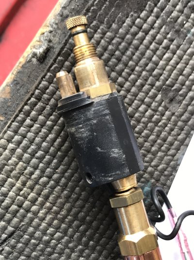
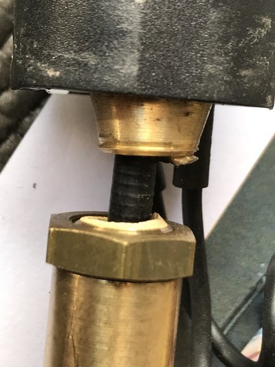
Without this forum and the people willing to share their knowledge and help, I wouldnt have stood a chance at diagnosing the problem. Thanks to the helpful suggestions from Eddie49, Stanbester and Seadog and following their systematic advice I think I have found the problem. I opened up the torch and all was looking good and clean, but then I noticed this: At the connector end the contact shroud has snapped, so a new torch is on its way and hopefully I should be welding again, and thanks to you guys I have a much better idea of how it all works too and might know what to do next time. Hope this post is useful to others too.
That is a good result; I am glad that you were able to track down the fault. I suppose that a fracture started in the brass sleeve where the screw thread had been cut.
New torch fitted and everything is working again. I guess over the years, the way Euro torch connections stick out it probably gets clouted now and again. This was a Murex torch so could have been the original, could be 20+ years old. Thanks to everyone for all the help