dave.armstrong11@btopenwo
New Member
- Messages
- 9
- Location
- Durham, NE England
Hi,
I normally hang out on the LandyZone Discovery forum for my D4 with occasional forays into the Defender world when helping my youngest with his TD5 110. I do have other cars, and as you can imagine - problems. It has been suggested on there that I try this forum for help, it was said that there are some knowledgeable guys on here.
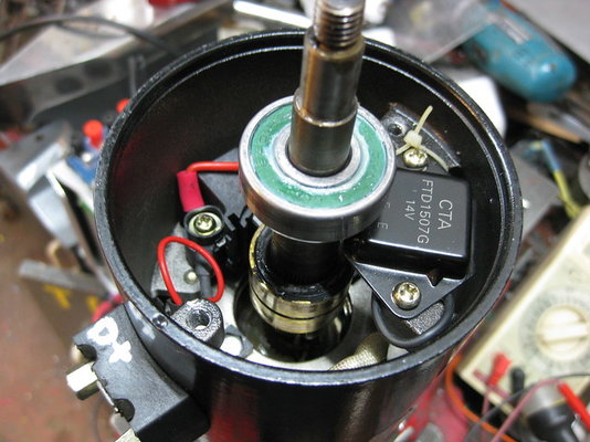
Latest problem is an alternator problem on an Austin 7. Yes I know they're supposed to have a dynamo but they were 6v, crap at charging and fragile. A company made some 'look alike' 12v alternators for these as a retrofit which is what I've got. This installation is more complex to change out compared to a normal belt driven one as it is gear driven with the distributor coming off the other end, which also makes it a pain in the **** to remove and refit/set up. The company have stopped making it and withdrawn all support.
Mine did originally work and nicely balanced the ammeter reading but then the red light started flickering with intermittent charging and eventually became always there. The voltage at the battery does not rise with the alternator running.
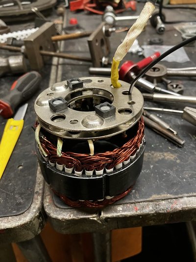
I've stripped it down (a few times in fact, I'm getting good at it) and can't find a fault. Can I draw on the enormous collective experience of those on this forum? Can you help please, am I missing something stupidly obvious?
The rotor coil has a good 4 ohms continuity out through the sliprings and brushes (which I manged to renew with a generic brush box item). The stator coil tests out similarly, though I haven't split out the separate coils in it to test individually. The diode pack has continuity in one direction and a very large resistance in the opposite direction. I've tried different internal regulators, cutting and grafting them from proprietary items (but can't work out which way to connect the two live wires - but neither alternative brings the alternator back to life). The alternator has a good earth to the engine and back to the battery.
If there's something down I'll have to either fix it myself or graft in a spare from something else though the rotor, stator and diode pack are very bespoke to the very small 3.5'' diameter body.
Am I missing something or not testing an aspect correctly and meaningfully?
Can you please advise how to test out each of these components?
Thank you, Dave


