


You are using an out of date browser. It may not display this or other websites correctly.
You should upgrade or use an alternative browser.
You should upgrade or use an alternative browser.
sip welder mods
- Thread starter Bluekoop
- Start date
the_chad_75
New Member
- Messages
- 1
Bluekoop
Sorry to sound stupid, but I understand why the capacitor is there, I don't understand what the mosfet and diode do in your circuit.
Sorry to sound stupid, but I understand why the capacitor is there, I don't understand what the mosfet and diode do in your circuit.
I'm in Brisbane and got the torch from "State of the arc" they are at Capallaba. I did ring the Binzel supplier in Aus. and he gave me contacts for a supplier in Brisbane but i went with the one i have(Parweld) as it was a bit cheaper.
Realise this is a little late but for the Ozzies on here I find the online trader "Bobthewelder" to be quite good and competatively priced
http://www.bobthewelder.com.au/home.php?xid=fd3f6cae3d9f7aed09a553b4eff3c0e9
I bought a SIP replacemnet torch from him and I see he has the Euro torch conversion kit as well
After much stuffing about i think i have got the wiring diagram. Now i know nothing about electronics so this is just a guess at what i thought might work
Its a long time since this this was posted, but I thought I'd update it with my findings
I tried making this mod, with the exact same components..but couldn't make it work with just the bits listed
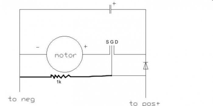
.... but with the addition of a 1k resistor and a change to the connections on the MOSFET it sprang into life !
The capacitor increases the effective torque of the motor and also smooths any hesitation when the arc is struck.
The Mosfet disconnects the capacitor from the motor when the trigger is released (if this didn't happen, the capacitor makes the motor run-on for almost a second !)
The resistor is needed to pull the gate of the mosfet down., otherwise it can float and will not switch off ...
Modified circuit layout below.
Its a long time since this this was posted, but I thought I'd update it with my findings
I tried making this mod, with the exact same components..but couldn't make it work with just the bits listed
.... but with the addition of a 1k resistor and a change to the connections on the MOSFET it sprang into life !
The capacitor increases the effective torque of the motor and also smooths any hesitation when the arc is struck.
The Mosfet disconnects the capacitor from the motor when the trigger is released (if this didn't happen, the capacitor makes the motor run-on for almost a second !)
The resistor is needed to pull the gate of the mosfet down., otherwise it can float and will not switch off ...
Modified circuit layout below.
heya spiyda, i dunno why mine works and yours didnt but i will try your mod anyway to see if there is a difference. Is it just the run on that was the problem? or was there other problems?
I tried to use mine a little while ago(i now have a new welder) and it didnt seem to be running right, i just figured it was me after using a good welder for a while!

edit: I've just noticed your legs on the mosfet have the motor as the source? how come?
Realise this is a little late but for the Ozzies on here I find the online trader "Bobthewelder" to be quite good and competatively priced
http://www.bobthewelder.com.au/home.php?xid=fd3f6cae3d9f7aed09a553b4eff3c0e9
I bought a SIP replacemnet torch from him and I see he has the Euro torch conversion kit as well
Thanks for the link wombat, ive been looking for a place to get parts for my plasma for a bit and he is quite well priced.
Bluekoop
Sorry to sound stupid, but I understand why the capacitor is there, I don't understand what the mosfet and diode do in your circuit.
probably a bit late, the mosfet is just a switch, bit like a relay and the diode is there to stop the charged capacitor keeping the mosfet "on" when you let go of the trigger.
The Mosfet source leg, hooks to the source of electrons, the negative side of the power source.heya spiyda, i dunno why mine works and yours didnt but i will try your mod anyway to see if there is a difference. Is it just the run on that was the problem? or was there other problems?
I tried to use mine a little while ago(i now have a new welder) and it didnt seem to be running right, i just figured it was me after using a good welder for a while!
edit: I've just noticed your legs on the mosfet have the motor as the source? how come?
The drain leg drains the negative electrons into the positive side of the power source.
Robert
The Mosfet source leg, hooks to the source of electrons, the negative side of the power source.
The drain leg drains the negative electrons into the positive side of the power source.
Robert
ok, you might have to describe it a bit better.
By my drawing the source is the power(+) from the board that would normally go straight to the motor, it charges the cap and turns the transistor "on". when the trigger is let go the transistor turns off leaving the cap with the charge ready for next time when you pull the trigger. The cap is basically a battery in DC. The diode is there to stop the charged cap from keeping the transistor on and causing the cap to discharge to the motor(and causing run on).
MOD - revised circuit here:- (Post #24)
http://www.mig-welding.co.uk/forum/showthread.php?t=9206&page=3
Last edited by a moderator:
"Drain" hooks to positive,"Source" hooks to negative,"Gate" switches "on" with positive voltage.
Like this.:http://brunningsoftware.co.uk/FET.htm
Robert
Like this.:http://brunningsoftware.co.uk/FET.htm
Robert
"Drain" hooks to positive,"Source" hooks to negative,"Gate" switches "on" with positive voltage.
Like this.:http://brunningsoftware.co.uk/FET.htm
Robert
Are mosfets flow directional like diodes?(being that they are semi-conductors)
heya spiyda, i dunno why mine works and yours didnt but i will try your mod anyway to see if there is a difference. Is it just the run on that was the problem? or was there other problems?
I tried to use mine a little while ago(i now have a new welder) and it didnt seem to be running right, i just figured it was me after using a good welder for a while!
edit: I've just noticed your legs on the mosfet have the motor as the source? how come?
The motor has to be connected to the source as it always goes to the negative side.. as mentioned above.. it goes to the source of the electrons...
I reckon yours is probably wired the same as in my diagram if an electronics bloke did it... but it was probably hard to see which leg was which when you drew the diagram..
The resistor is there to pull the gate down when the power is disconnected.. without it, when the power went off, the gate floated up and didn't turn off the mosfet... resulting in run on... that might not be the case with all mosfets as they vary a bit.. but it was with mine..
The welder works a treat now on high power.. (I'm welding a rollcage up) but I haven't tried it on thin gauge stuff since the changes..
I must admit.. I scratched my head a bit when I worked from your diagram.. I'm not an electronics expert by any means... I fitted the bits and it didn't work right off... so I "phoned a friend" :-) he soon put me on the right track... :-)
Chris
Well i welded the curcuit together but the old man inlaw told me what to do so no doubt i have just stuffed up the drawing, especailly since they seem to be flow directional. Might have to change the drawing!
Hey I know you are upside down, down there in Oz ... maybe the electrons go the other way too
seriously, even though I do the odd bit of hobby electronics, I didn't get it til I got my electronics expert mate to look at it..
the drawing I did with the resistor (from the working circuit which is thanks to him, not me) works a treat... just switch it for the original
Very late to this post but I have some trailer panel repairs and my primary mig welder is too hot so dusted off old SIP and want to try and improve it using details in this thread.
Curtain wire steel liner mod and wire feed roller brace mod were very easy to do.
For the capcitor and disconnect switch mod -
I am not sure if the circuit sits between the motor and power source or if it is parallel to the supply, ie the original motor wires are not disconnected? Can someone clarify.
I blew the power transistor and 22R resistor on the motor control board with my first bodgy attempt (not sure how). Fixed that and now have the capacitor control circuit on a breadboard and have it working as a voltage controlled switch. Just want to double check installation instructions before I go again?
Ta
I see that the electron flow vs conventional flow confusion might have confused the thread!
My other question relates to the maximum safe gate voltage for the MOSFET. As the motor voltage ranges from 13-40v on my machine, and the maximum Vgs is 20v for this MOSFET - not sure why these do not fry at high wire feed speeds? Would an 18v zener diode from gate to ground provide protection?
Sean
Another 602 fan
- Messages
- 1,447
if you run it with a separate power supply for the feed then you take away the problem that is the massive and fluctuating wire speed voltage to the motor.My other question relates to the maximum safe gate voltage for the MOSFET. As the motor voltage ranges from 13-40v on my machine, and the maximum Vgs is 20v for this MOSFET - not sure why these do not fry at high wire feed speeds? Would an 18v zener diode from gate to ground provide protection?
KISS keep it simple stu....suppose the level of "Simple" depends on your understanding of electronics...i just melt metal for fun, the extra 240-24vtransformer mod at the start of this thread did just fine and allowed me to melt thin metal in a consistent fashion.


