


dozybee
New Member
- Messages
- 6
- Location
- Isle of Man
Problem: Our island domestic voltage sits around 250 V. My Sealey EM130XT.V2 on the lowest power setting blasted holes through my new Transit body panels ( amateur welder problem ? ). An even lower setting would be useful.
Solutions:
1. Using info from the Mig welder forums, modify the wire feeder electrics to get a stable feed.
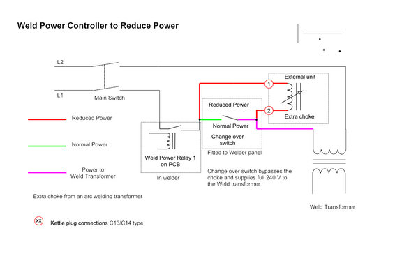
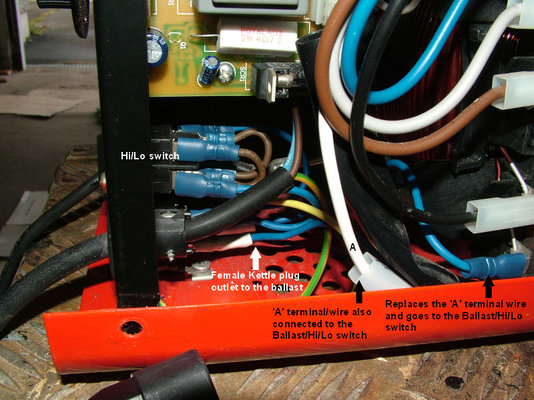
2. Install a 'Ballast' in the line to the primary winding of the weld transformer. This should reduce the
weld power to a suitable level ( Hopefully ).
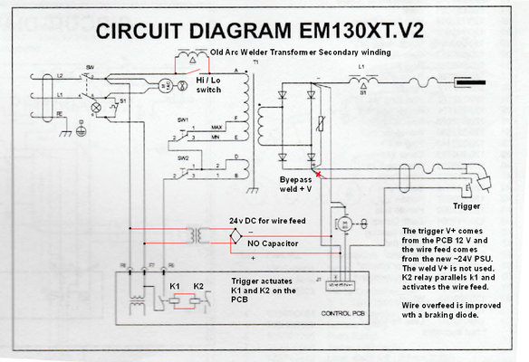
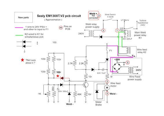
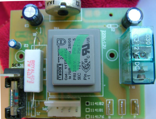
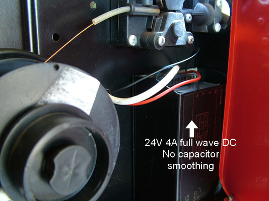
To achieve Solution 1 required some knowledge of the workings of the PCB. I produced a reasonable schematic with my mods to get a controllable wire feed. This wire feed has an SCR so I assumed that it would require an unsmoothed full wave rectified ~20v 4a DC supply. ( No filter capacitor needed )
The wire "ran on" at first but a diode across the wire feeder motor appears to have reduced that.
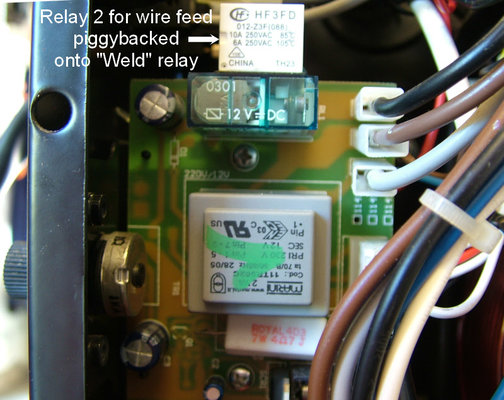
My wire feeder relay came from a retired microwave oven and is a 12v one. It is "piggybacked" with the weld transformer relay.
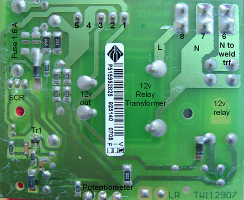
The PSU was an old +24, -24v 2A unit. The windings were parallelled ( 4A ) and a bridge rectifier fitted. The fuse on the PCB appeared to be rated at 1.6 amps so my 4 amps was a bit of an overkill.
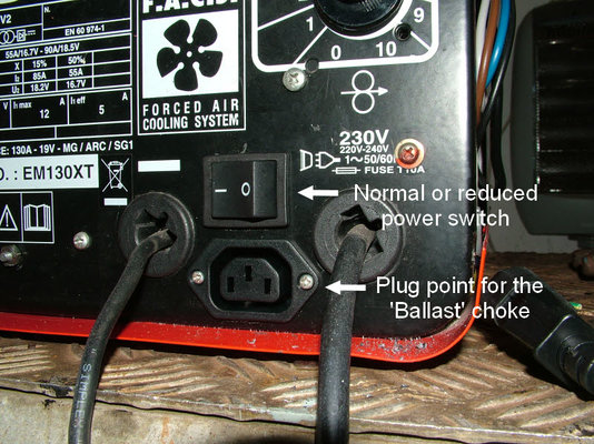
Solution 2 was a lot simpler except for fitting the switch and the power outlet. The 'Ballast' came from an old arc welder transformer. Trying the primary windings on the arc welding transformer was too extreme. Using the secondary winding seemed to work better. Now for a box for it!
The Transit panels were already fitted by the time the welder mods were completed. Time constraints precluded any really definitive tests. However a delicate repair job requiring the lowest setting and .6 mm wire came up.
The wire speed ended up at setting 2~3 and the arc appeared more "sedate". The lower current
made working with the thin metal a lot more manageable.
Reverse engineering of the PCB was not thorough but it was sufficient to modify the wire feed circuitry.
Overall, using the Mig welding forum as a starting point, I am rather satisfied with the outcome.
The Sealey schematic wiring is well marked out. The first order of the day would be a good
degree of electrical know how. The next job would be getting familiar with where everything goes.
240 V ac can/will be lethal. Please take care with earthing and other electrical matters.
Hopefully this project will cast more light on the wire feed and power problems faced by owners of "Budget" MIG welders.
Solutions:
1. Using info from the Mig welder forums, modify the wire feeder electrics to get a stable feed.
2. Install a 'Ballast' in the line to the primary winding of the weld transformer. This should reduce the
weld power to a suitable level ( Hopefully ).
To achieve Solution 1 required some knowledge of the workings of the PCB. I produced a reasonable schematic with my mods to get a controllable wire feed. This wire feed has an SCR so I assumed that it would require an unsmoothed full wave rectified ~20v 4a DC supply. ( No filter capacitor needed )
The wire "ran on" at first but a diode across the wire feeder motor appears to have reduced that.
My wire feeder relay came from a retired microwave oven and is a 12v one. It is "piggybacked" with the weld transformer relay.
The PSU was an old +24, -24v 2A unit. The windings were parallelled ( 4A ) and a bridge rectifier fitted. The fuse on the PCB appeared to be rated at 1.6 amps so my 4 amps was a bit of an overkill.
Solution 2 was a lot simpler except for fitting the switch and the power outlet. The 'Ballast' came from an old arc welder transformer. Trying the primary windings on the arc welding transformer was too extreme. Using the secondary winding seemed to work better. Now for a box for it!
The Transit panels were already fitted by the time the welder mods were completed. Time constraints precluded any really definitive tests. However a delicate repair job requiring the lowest setting and .6 mm wire came up.
The wire speed ended up at setting 2~3 and the arc appeared more "sedate". The lower current
made working with the thin metal a lot more manageable.
Reverse engineering of the PCB was not thorough but it was sufficient to modify the wire feed circuitry.
Overall, using the Mig welding forum as a starting point, I am rather satisfied with the outcome.
The Sealey schematic wiring is well marked out. The first order of the day would be a good
degree of electrical know how. The next job would be getting familiar with where everything goes.
240 V ac can/will be lethal. Please take care with earthing and other electrical matters.
Hopefully this project will cast more light on the wire feed and power problems faced by owners of "Budget" MIG welders.
-
 1SealeyCkt2.jpg130.1 KB · Views: 1,189
 -
 2SealyModdedCircuit.jpg168.4 KB · Views: 701
 -
 3Welder Choke.jpg122.6 KB · Views: 619
 -
 4pcbbottom.jpg159.4 KB · Views: 537
 -
 5pcbtop.jpg112.5 KB · Views: 551
 -
 6PSUforFEED.jpg111.5 KB · Views: 489
 -
 7Weld PCB.jpg139.8 KB · Views: 507
 -
 8Ballast point.jpg143 KB · Views: 508
 -
 9XtraBallast.jpg191.2 KB · Views: 520
 -
 10BallastinUse.jpg169.9 KB · Views: 594


