


You are using an out of date browser. It may not display this or other websites correctly.
You should upgrade or use an alternative browser.
You should upgrade or use an alternative browser.
Sealey 170/1 Voltage control switch
- Thread starter brading
- Start date
mike 109444
Member
- Messages
- 4,885
Hi Brading (and welcome) I see you posted a similar post up a few weeks ago and got no replys so will try to help.
The A1 A2 L1 ect are they on the wires or on the switch?
You have a bunch of stiff (?) enameled wires, most coming from the transformer and maybe one or two coming from the mains input cable maybe via a seperate on/off switch?
You will need a meter with ohms setting on it.
Can you post pics of the switch (if you have macro function on camera use that for clear pics)
Then we can begin..... : )
linuxfreak
New Member
- Messages
- 5
Might help......
Might this help? Seems Sealey, Chicago Electric and PowerFist all share the same "parents"

My own PowerFist MIG-136 looks like the Chicago Electric MIG-151 and the Sealy MightyMIG 150, name labels changed to "sucker" the innocent!

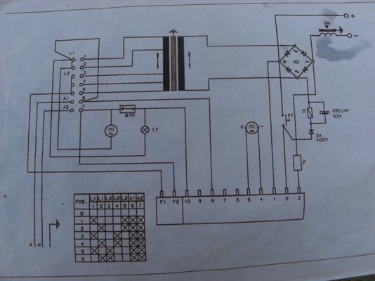
Here's the schematic from the discontinued Chicago Electric MIG-171, 240V single phase, shows the switch contact arrangement used.
George

Might this help? Seems Sealey, Chicago Electric and PowerFist all share the same "parents"
My own PowerFist MIG-136 looks like the Chicago Electric MIG-151 and the Sealy MightyMIG 150, name labels changed to "sucker" the innocent!
Here's the schematic from the discontinued Chicago Electric MIG-171, 240V single phase, shows the switch contact arrangement used.
George
linuxfreak
New Member
- Messages
- 5
Another......
Found I had a manual for the SuperMIG 180, had this wiring diagram and switch chart.

Hope one of these might help.
George
Found I had a manual for the SuperMIG 180, had this wiring diagram and switch chart.
Hope one of these might help.
George
Sealey 170/1 Votage control switch
Hi Mike 109444
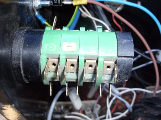
The nubers were originally on the switch, though most of them have disappeared leaving only nuber 1. I have a bunch of wire coming from the transformer, 2 single and 3 lots of 2 wires. I have wires coming from the Wire speed control switch, from the cooling fan and 2 from an on / off switch. none of these are marked. I also have a schematic wiring diagram that I got from Sealey technical though the were not able to help with the switch number as the switch has been updated. On the wiring diagram the live and neutral are marked as R and N so am not sure which is Live and which is Neutral.
Hi Linuxfreak
Thank for the diagrams
For some reason the photos did not Upload will try again
Hi Mike 109444
The nubers were originally on the switch, though most of them have disappeared leaving only nuber 1. I have a bunch of wire coming from the transformer, 2 single and 3 lots of 2 wires. I have wires coming from the Wire speed control switch, from the cooling fan and 2 from an on / off switch. none of these are marked. I also have a schematic wiring diagram that I got from Sealey technical though the were not able to help with the switch number as the switch has been updated. On the wiring diagram the live and neutral are marked as R and N so am not sure which is Live and which is Neutral.
Hi Linuxfreak
Thank for the diagrams
For some reason the photos did not Upload will try again
Last edited:
mike 109444
Member
- Messages
- 4,885
Reread your post 5 and see that you say the wires are not marked. that will make it tougher.
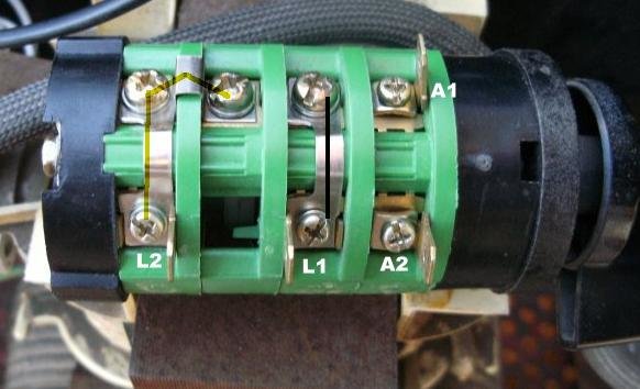
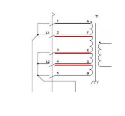
What I have worked out so far see pic
note the dotted line will be a linking wire going from L1 to pin 6 once we have figured rest of pins.
What I have worked out so far see pic
note the dotted line will be a linking wire going from L1 to pin 6 once we have figured rest of pins.
mike 109444
Member
- Messages
- 4,885
Set power switch to 1, If you then meter between L1 and the pins on other side (grubby ones!) you should find it connects to the pin marked 1 (the only one marked!!) Now meter between L2 and pins on other side. should connect to pin 5.
Now set to power 2 Then connect meter between L1 and pins on other side till you find a connection. This should be pin 2.
Now set to power 3 Then connect meter between L1 and pins on other side till you find a connection. This should be pin 3. Now meter between L2 and pins on other side. should connect to pin 4.
If the above does not work out let me know and will look at again.
If correct then will start looking at wires (pics of wires coming from transformer will help)
Last edited:
mike 109444
Member
- Messages
- 4,885
Meter between A1 and grubby side.(any power setting except off!) connection is pin 6.
Meter between A2 and grubby side.(any power setting except off!) connection is pin 7.
Meter between A2 and grubby side.(any power setting except off!) connection is pin 7.
Sealey 170/1 Votage control switch
Hi Mike
This is the results I got
Pos 1 L1 connects to 1 L2 connects to 5
Pos 2 L1 connects to 2 L2 connects to 5
Pos 3 L1 connects to 1 L2 connects to 4
Pos 4 L1 connects to 2 L2 connects to 4
Pos 5 L1 connects to 1 L2 connects to 3
Pos 6 L1 connects to 2 L2 connects to 3
In pos 1 to 6 A1 connects to 6
In pos 1 to 6 A2 connects to 7
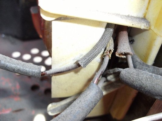
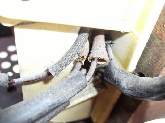
There are five sets of wires coming out of the transformer 2 with a single
wire ending in a spade terminal and 3 sets of two wire each wire ending in a
spade terminal.
Cheers Paul
Hi Mike
This is the results I got
Pos 1 L1 connects to 1 L2 connects to 5
Pos 2 L1 connects to 2 L2 connects to 5
Pos 3 L1 connects to 1 L2 connects to 4
Pos 4 L1 connects to 2 L2 connects to 4
Pos 5 L1 connects to 1 L2 connects to 3
Pos 6 L1 connects to 2 L2 connects to 3
In pos 1 to 6 A1 connects to 6
In pos 1 to 6 A2 connects to 7
There are five sets of wires coming out of the transformer 2 with a single
wire ending in a spade terminal and 3 sets of two wire each wire ending in a
spade terminal.
Cheers Paul
Last edited:
mike 109444
Member
- Messages
- 4,885
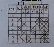
Paul the results of your metering of the switch shows that it is as the super mig 180 diagram that Linuxfreak (George) posted which is very much same as the diagram you have. Not sure if you can understand the switch chart (one with the x's). don't worry if you do not. Any way the wires from the transformer are thus:
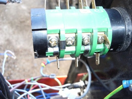
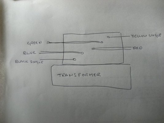
One of the single wires is 1 in pic below and other is 5
The double wires are loops out from the transformer and back again (refered to as a tap) indicated by the black line out and the red line back in. These are for the 2,3 and 4.
Problem now is working out which single wire is 1 and which is 5, also which loop out and back is 2,3 and 4!
The problem is that there is very little difference between the resistance of the wires in the transformer (most meters won't show the small amount of difference between windings)
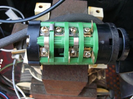
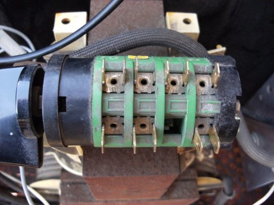
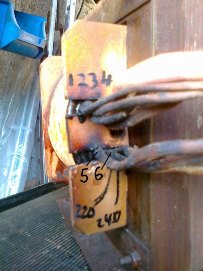
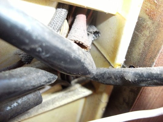
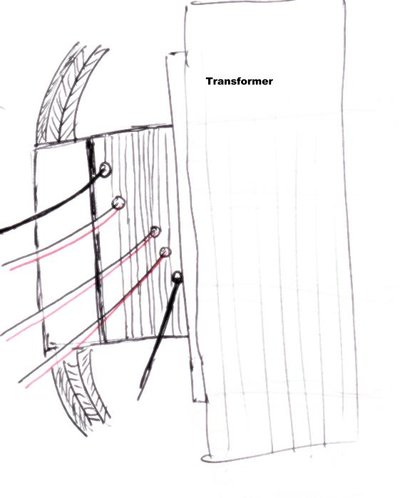
If you look at the second pic it is of my transformer (before I rewound it as it was fried!!) If you can get a pic of where the wires come ot of transformer it may be possible to workout from there level in the winding which is which. Failing that I will post in a min how you might meter to workout which is which. Will do sketch
One of the single wires is 1 in pic below and other is 5
The double wires are loops out from the transformer and back again (refered to as a tap) indicated by the black line out and the red line back in. These are for the 2,3 and 4.
Problem now is working out which single wire is 1 and which is 5, also which loop out and back is 2,3 and 4!
The problem is that there is very little difference between the resistance of the wires in the transformer (most meters won't show the small amount of difference between windings)
If you look at the second pic it is of my transformer (before I rewound it as it was fried!!) If you can get a pic of where the wires come ot of transformer it may be possible to workout from there level in the winding which is which. Failing that I will post in a min how you might meter to workout which is which. Will do sketch
mike 109444
Member
- Messages
- 4,885
Paul I forgot to ask how did the wiring end up like this ??
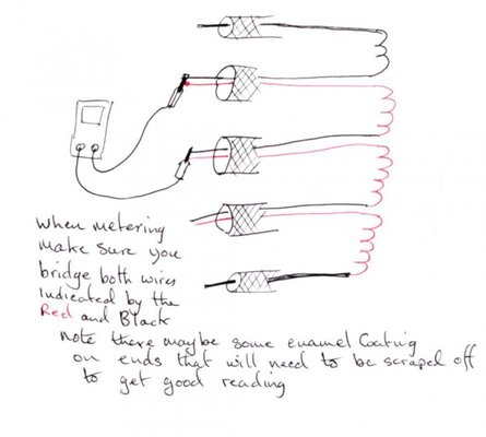
Asuming your meter will show the difference between small differences of resistance...
Set you meter to it's lowest resistance range (0 to 10? or 0 to 100 first is best if avi).
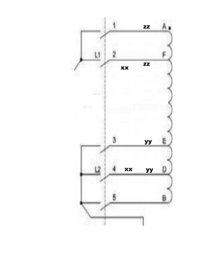
refering to the pic below (I have streched it to better repesent the longer winding) you need to find xx to xx first.
So taking just the 3 wires that are doubled meter between two pairs and make a note of reading (get good contact on the wires for good reading) now meter between one of the two that you have just metered and the one that had not been, note the reading. Now meter between the one that had not been and the second one, note reading . Yep I know this sounds confusing but if I start to call them 1, 2 and 3 it would be even more confusing!!
From the above the pair that had the highest reading are xx and xx.
Now need to sort yy to yy. From the values noted above the pair that had the lowest reading are yy, yy There for the wire that does not make yy, yy is number 2 (mark it as so with tape?)
The other wire that made xx, xx must be 4 (mark it as so)
The remaining wire is 3 (mark it as so)
Now need to sort zz, zz. As you now know which is number 2, if you meter between this and one of the two single wires then the other. One should give a lower reading as this is zz, zz. and tells you that the single wire that gave the lower reading is number 1 (mark it as so)
Therefore the remaining wire is number 5
Phew...
This will all depend on your meter and metering.
There is another methord but that involves applying voltage to the wires and could be dangerous....(I use a breakout box for such work and know to keep one hand in your pocket, as per old style tv engineers)
Let me know how above goes
Asuming your meter will show the difference between small differences of resistance...
Set you meter to it's lowest resistance range (0 to 10? or 0 to 100 first is best if avi).
refering to the pic below (I have streched it to better repesent the longer winding) you need to find xx to xx first.
So taking just the 3 wires that are doubled meter between two pairs and make a note of reading (get good contact on the wires for good reading) now meter between one of the two that you have just metered and the one that had not been, note the reading. Now meter between the one that had not been and the second one, note reading . Yep I know this sounds confusing but if I start to call them 1, 2 and 3 it would be even more confusing!!
From the above the pair that had the highest reading are xx and xx.
Now need to sort yy to yy. From the values noted above the pair that had the lowest reading are yy, yy There for the wire that does not make yy, yy is number 2 (mark it as so with tape?)
The other wire that made xx, xx must be 4 (mark it as so)
The remaining wire is 3 (mark it as so)
Now need to sort zz, zz. As you now know which is number 2, if you meter between this and one of the two single wires then the other. One should give a lower reading as this is zz, zz. and tells you that the single wire that gave the lower reading is number 1 (mark it as so)
Therefore the remaining wire is number 5
Phew...
This will all depend on your meter and metering.
There is another methord but that involves applying voltage to the wires and could be dangerous....(I use a breakout box for such work and know to keep one hand in your pocket, as per old style tv engineers)
Let me know how above goes
Hi Mike
I do not know the reason the wires taken off as I got the welder from a friend who got it from someone else. My meter only goes down to 200 I tried getting reading and the only readings I got were between first pair 1.1, second pair 0.6, third pair nothing. The switch chart with the X's is the easy bit to understand it is the rest that is baffling. Knew a guy years ago and remember him mentioning something about the hand in the pocket when he was working on TV's
Cheers Paul
mike 109444
Member
- Messages
- 4,885
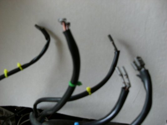
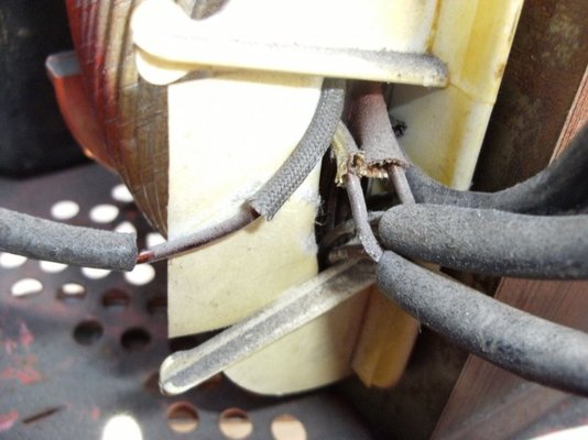
Paul when you say you got "nothing" on the third pair do you mean no reading or 00.0 which is a reading! if it was 00.0 then that is the yy, yy. if you did get nothing then either not getting good connections (see pic) or transformer may be duff. See also if you get a reading when you meter between the two single wires?
mike 109444
Member
- Messages
- 4,885
Sealey 170/1 control switch
Hi Mike
Sorry about the delay in answering but I had to go away unexpectedly. Borrowed a better meter so have got some new readings. I marked the double cables one Blue, one Red and one Green. The single cables one Yellow and one Black. The results of testing between cables was.
Blue and Green 001.0
Blue and Red 000.8
Green and Red 000.4
Blue and Yellow 001.4
Red and Yellow 000.7
Green and Yellow 000.4
Blue and Black 000.3
Red and Black 000.8
Green and Black 001.2
mike 109444
Member
- Messages
- 4,885
Paul from your readings (I had hoped there would be a bigger difference) If they are correct then I belive
Black = 1
Blue = 2
Red = 3
Green = 4
Yellow = 5
If when you are ready to apply power to the machine you can put a meter on the output of the transformer and check that the voltage out is stepping up or down as per the settings on the switch ie power setting 1 should give about say 16vAC power 2 should give say 18vAC and so on up through all 6 if not then may have to recheck.
Work safe be ready to turn off power! As you don't know the history of this welder.
Much more to rewire?


