


You are using an out of date browser. It may not display this or other websites correctly.
You should upgrade or use an alternative browser.
You should upgrade or use an alternative browser.
New welding table build.
- Thread starter taz00
- Start date
Now as I slowly build my man-cave, the time has come for a proper welding table.
I always liked the buildpro, demmeler etc type of tables but they were too expensive for me so I thought about making one myself.
So far I have ordered 8pcs of 198x1000mm 20mm thick plate as well as the square tubing (1pc 6m 60x60x5mm and 1pc 60x60x3.2mm).
I got an estimate to have the plates cut and drilled on a water jet but the price was really high (understandably) so I figured I would get myself a magnetic drill for the same price and I get to keep it in the end.
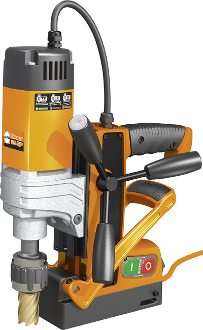 Alfra RB 35 SP by Taz00, on Flickr
I want to drill 16mm holes in a 50mm square pattern. This equates to 4x20=80 holes per plate so 640 holes for the whole table :dizzy:
Here is an initial sketch of the table. Do not be too hard on me, I started learning to use solidworks last week (boy is it completely different to autocad...)
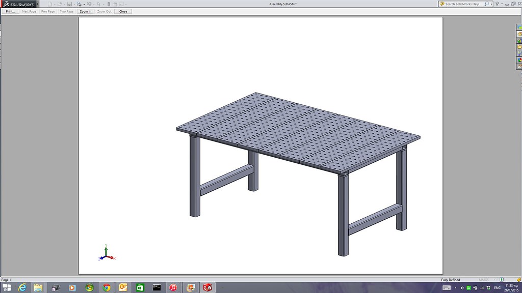 Screenshot 2015-01-26 11.33.58 by Taz00, on Flickr
The plates will be bolted on the top of the table and I will make an insert with strips and water tray that could be placed on top instead of 2-3 plates and be used for plasma cutting (no drawing on that so far, I will figure out the exact configuration after the table is built.
As far as tooling is concerned for starters I intend on modifying a lot of clamps to something like this http://www.stronghandtools.com/build...rta_clamps.php
I have a lathe (and a vertical milling slide) so it should not be difficult at all.
I also want to make some stops and rest buttons and go from there.
Generally the idea is to make most of the accessories myself. The 16mm diameter was selected since both buildpro and demmeler use it so I could buy a particular accessory from them if I need it and cannot make it myself.
Holes will not be threaded.
I will try to take some pictures as the build progresses
I always liked the buildpro, demmeler etc type of tables but they were too expensive for me so I thought about making one myself.
So far I have ordered 8pcs of 198x1000mm 20mm thick plate as well as the square tubing (1pc 6m 60x60x5mm and 1pc 60x60x3.2mm).
I got an estimate to have the plates cut and drilled on a water jet but the price was really high (understandably) so I figured I would get myself a magnetic drill for the same price and I get to keep it in the end.
Alfra RB 35 SP by Taz00, on FlickrI want to drill 16mm holes in a 50mm square pattern. This equates to 4x20=80 holes per plate so 640 holes for the whole table :dizzy:
Here is an initial sketch of the table. Do not be too hard on me, I started learning to use solidworks last week (boy is it completely different to autocad...)
Screenshot 2015-01-26 11.33.58 by Taz00, on FlickrThe plates will be bolted on the top of the table and I will make an insert with strips and water tray that could be placed on top instead of 2-3 plates and be used for plasma cutting (no drawing on that so far, I will figure out the exact configuration after the table is built.
As far as tooling is concerned for starters I intend on modifying a lot of clamps to something like this http://www.stronghandtools.com/build...rta_clamps.php
I have a lathe (and a vertical milling slide) so it should not be difficult at all.
I also want to make some stops and rest buttons and go from there.
Generally the idea is to make most of the accessories myself. The 16mm diameter was selected since both buildpro and demmeler use it so I could buy a particular accessory from them if I need it and cannot make it myself.
Holes will not be threaded.
I will try to take some pictures as the build progresses
The drill arrived today and I also got the square tubing.
Did not get to do any serious work, just got to try out the drill.
So here are a few pictures:
What is the easiest way to mark the centre locations of the holes? Print the grid on your plotter and stick the paper on the top of the plate and then use a centre punch to mark them.
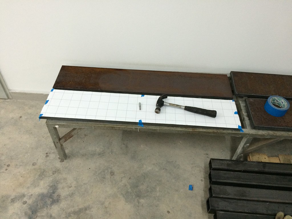 Untitled by Taz00, on Flickr
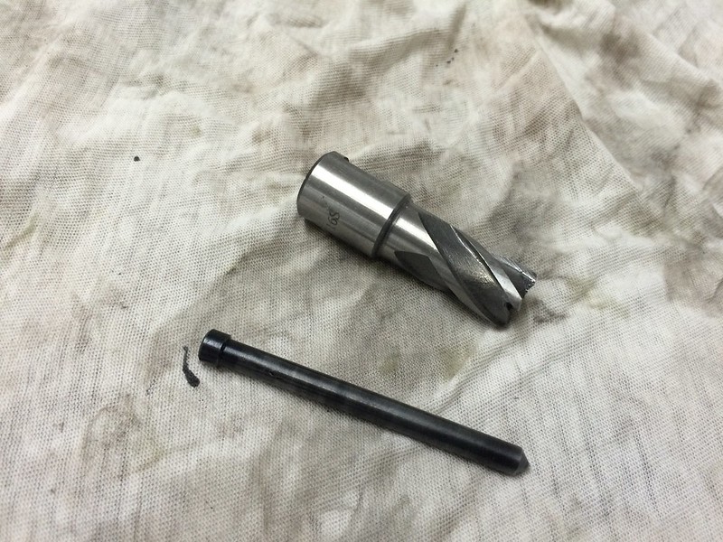
The centre punch is actually a bolt I turned down on my lathe with a hole drilled and a red tungsten inserted in it.
The new drill is awesome. The permanent magnet makes it able to be used on very thin material.
Q: What usually happens when you drill a hole with the mag drill upside down and someone stumbles on your cord and pulls it out of the socket?
A: NOTHING :lol:
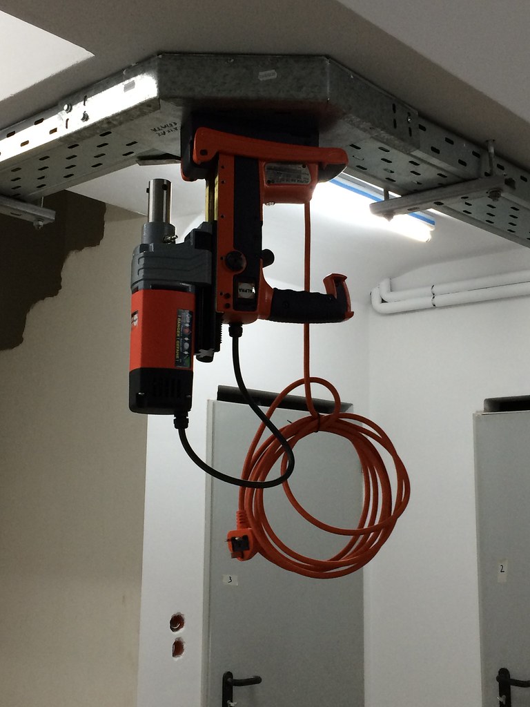 Alfra RB35 SP by Taz00, on Flickr
It takes very little effort to drill the holes, it is a lot easier than I anticipated. I need a lot more time to position the drill accurately than to drill the hole.
Here is a short video of the second hole being drilled
The coolant makes a mess of everything so I have to find some other area in my basement to do the drilling.
Will try and post more pics as I get it done.
Did not get to do any serious work, just got to try out the drill.
So here are a few pictures:
What is the easiest way to mark the centre locations of the holes? Print the grid on your plotter and stick the paper on the top of the plate and then use a centre punch to mark them.
Untitled by Taz00, on FlickrThe centre punch is actually a bolt I turned down on my lathe with a hole drilled and a red tungsten inserted in it.
The new drill is awesome. The permanent magnet makes it able to be used on very thin material.
Q: What usually happens when you drill a hole with the mag drill upside down and someone stumbles on your cord and pulls it out of the socket?
A: NOTHING :lol:
Alfra RB35 SP by Taz00, on FlickrIt takes very little effort to drill the holes, it is a lot easier than I anticipated. I need a lot more time to position the drill accurately than to drill the hole.
Here is a short video of the second hole being drilled
The coolant makes a mess of everything so I have to find some other area in my basement to do the drilling.
Will try and post more pics as I get it done.
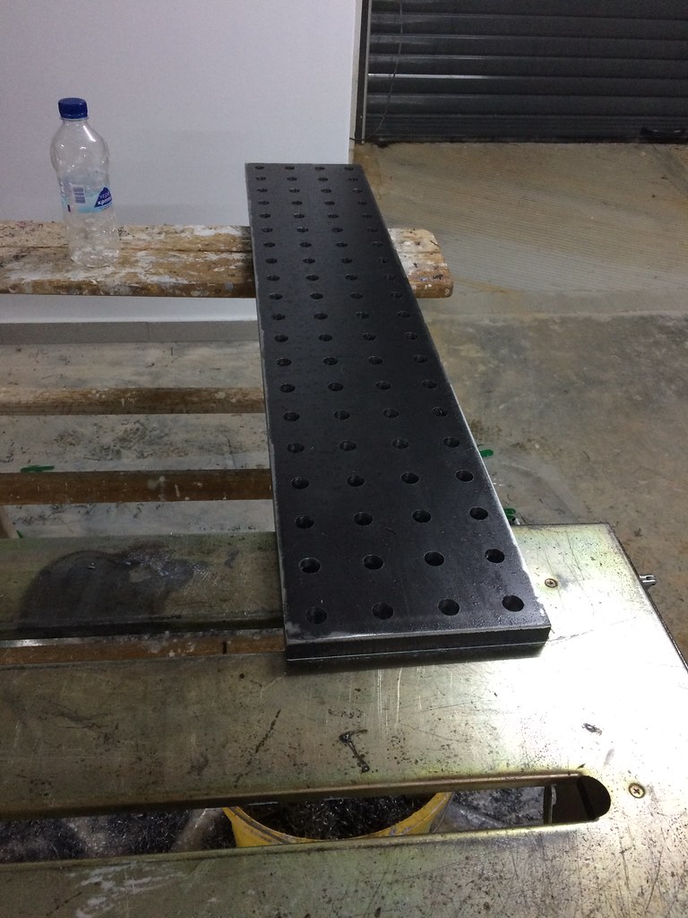
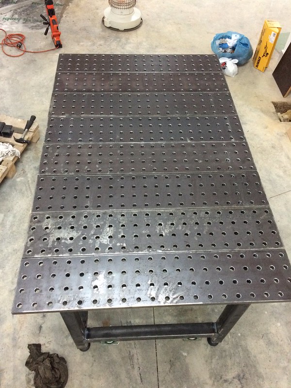
One down, seven to go :? I still need to countersink the holes though.
 Untitled by Taz00, on Flickr
A few observations:
I have regretted the fact I did not ask for the plates to be sandblasted. I spent all morning wire brushing the plates and they still look like ****. At least in the future I could always have them ground if I wanted to.
The fact that the centre pin has a small amount of play, combined with the accuracy of my centre punch marks (or lack of it) has lead to a variation in hole location up to 1mm. I guess if someone wants a better accuracy he would have to have the holes opened by cnc.
Untitled by Taz00, on FlickrA few observations:
I have regretted the fact I did not ask for the plates to be sandblasted. I spent all morning wire brushing the plates and they still look like ****. At least in the future I could always have them ground if I wanted to.
The fact that the centre pin has a small amount of play, combined with the accuracy of my centre punch marks (or lack of it) has lead to a variation in hole location up to 1mm. I guess if someone wants a better accuracy he would have to have the holes opened by cnc.
Last edited by a moderator:
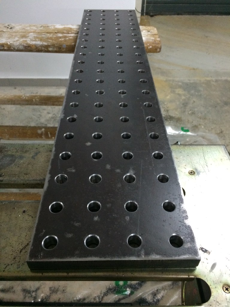
Today all I managed was to countersink the holes of the first plate (both sides) and mark the second plate.
 Untitled by Taz00, on Flickr
The good news, my marking was not off as much as I thought :mrgreen: . It turns out the steel ruler I used to check the location of my holes was not straight :cry:
Not that if it was off by 1mm would mean the end of the world, I would just live with it.
Untitled by Taz00, on FlickrThe good news, my marking was not off as much as I thought :mrgreen: . It turns out the steel ruler I used to check the location of my holes was not straight :cry:
Not that if it was off by 1mm would mean the end of the world, I would just live with it.
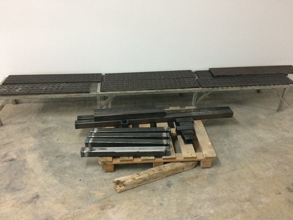
Slats and legs almost finished
 Welding table by Taz00, on Flickr
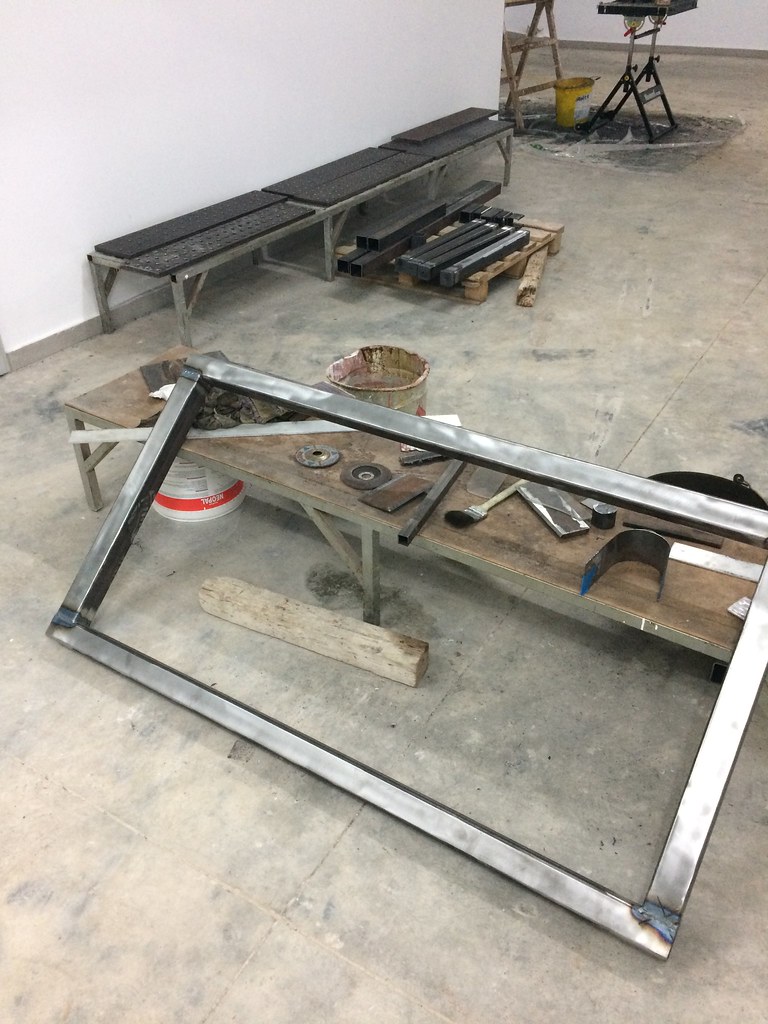
Top frame almost finished
 Welding table by Taz00, on Flickr
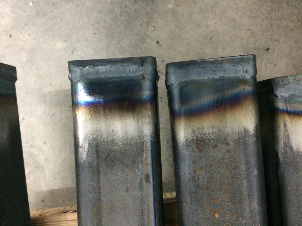
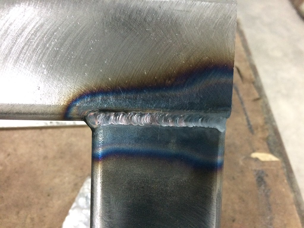
Some pics of the welds :roll: as I said I want to finish the table so went for speed before quality
 Welding table by Taz00, on Flickr
 Welding table by Taz00, on Flickr
The last weld is below flush on purpose, I wanted to keep filler to a minimum since it would interfere with the slats.
Even that way I had some problems with distortion since I do not have a big welding table to build my big welding table :lol: .
I had to cut and reweld 1-2 welds to straighten the top frame.
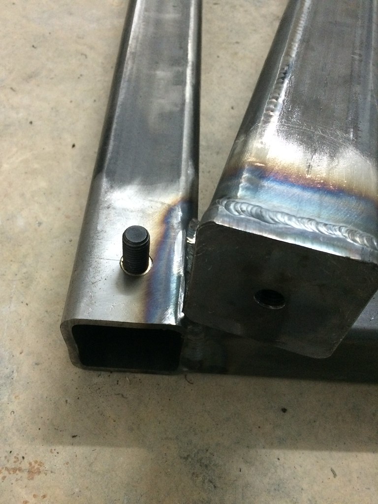
The legs have a 10mm plate welded on top and bottom with a 12mm threaded hole each.
The bottom will be used for the levelling feet and the top to attach the legs to the top frame.
Welding table by Taz00, on FlickrTop frame almost finished
Welding table by Taz00, on FlickrSome pics of the welds :roll: as I said I want to finish the table so went for speed before quality
Welding table by Taz00, on FlickrWelding table by Taz00, on FlickrThe last weld is below flush on purpose, I wanted to keep filler to a minimum since it would interfere with the slats.
Even that way I had some problems with distortion since I do not have a big welding table to build my big welding table :lol: .
I had to cut and reweld 1-2 welds to straighten the top frame.
The legs have a 10mm plate welded on top and bottom with a 12mm threaded hole each.
The bottom will be used for the levelling feet and the top to attach the legs to the top frame.
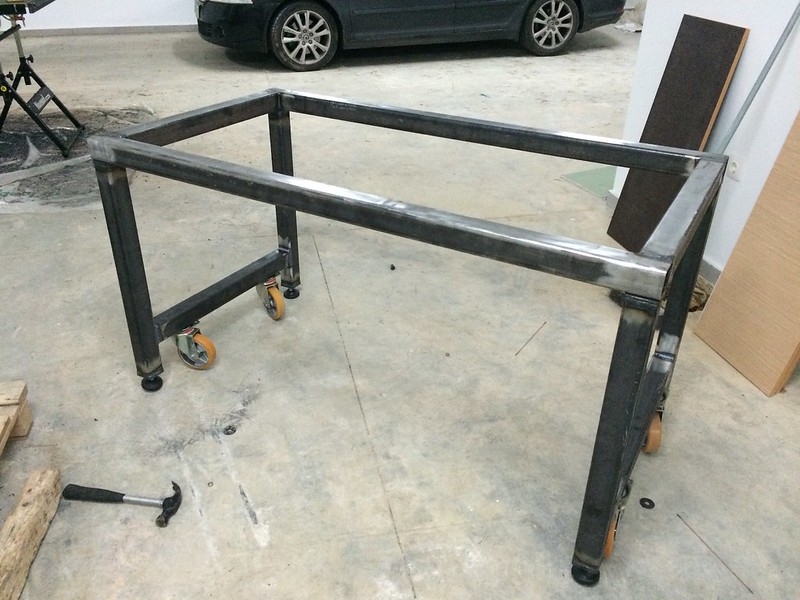
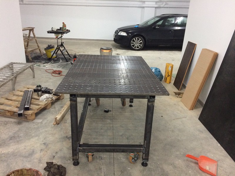
Today I managed to put in 4 hours after work.
Here is the frame in its current status.
 Welding table by Taz00, on Flickr
It looks almost finished but there is still a lot of work to do.
A small detail. The hole that the 12mm bolt that attaches the top frame to the legs passes through is 14mm. In order to keep it exactly centered during welding the cross braces, I made 2 small brass bushings. These were removed after welding and the threaded holes are now perfectly aligned to the holes on the top of the table for easy assembly/disassembly.
 Welding table by Taz00, on Flickr
Here is the frame in its current status.
Welding table by Taz00, on FlickrIt looks almost finished but there is still a lot of work to do.
A small detail. The hole that the 12mm bolt that attaches the top frame to the legs passes through is 14mm. In order to keep it exactly centered during welding the cross braces, I made 2 small brass bushings. These were removed after welding and the threaded holes are now perfectly aligned to the holes on the top of the table for easy assembly/disassembly.
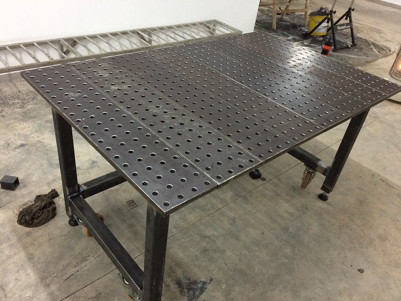
Welding table by Taz00, on FlickrTesting how it will look.
I still have to attach the slats to the table, weld holders for the angle grinders, paint the frame etc.
 Welding table by Taz00, on Flickr
 Welding table by Taz00, on Flickr
 Welding table by Taz00, on Flickr
This little sucker drilled 640 holes on 20mm thick steel and it looks like it could do as much without breaking a sweat.
 Welding table by Taz00, on Flickr
I still have to attach the slats to the table, weld holders for the angle grinders, paint the frame etc.
Welding table by Taz00, on FlickrWelding table by Taz00, on FlickrWelding table by Taz00, on FlickrThis little sucker drilled 640 holes on 20mm thick steel and it looks like it could do as much without breaking a sweat.
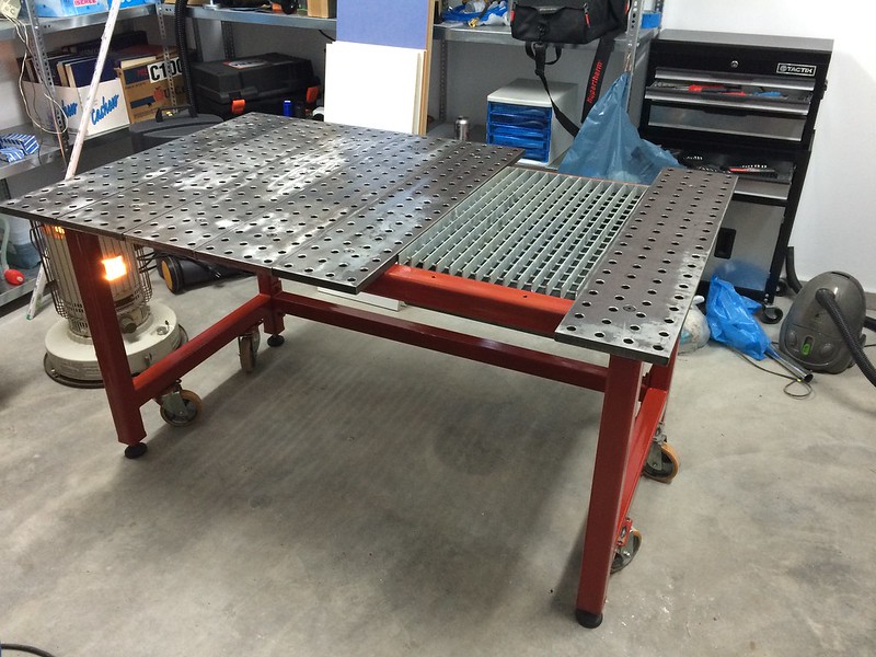
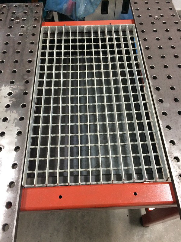
Welding table by Taz00, on FlickrIt is almost complete. Here shown with optional plasma cutting / stick welding grate and water bed.
 Welding table by Taz00, on Flickr
 Welding table by Taz00, on Flickr
 Welding table by Taz00, on Flickr
I still have to make hangers for the angle grinders etc but it is more or less finished.
Now to start making some tools for it. :lol:
Welding table by Taz00, on FlickrWelding table by Taz00, on FlickrWelding table by Taz00, on FlickrI still have to make hangers for the angle grinders etc but it is more or less finished.
Now to start making some tools for it. :lol:
Kent
Member
- Messages
- 9,992
- Location
- Bowland, Lanacshire,UK
As regards making I should make a perfect drilling template / jig. Mark out the old fashioned way first personally, check and treble check. Good luck with the project though. I am planning a far simpler affair myself as without CNC machining etc I fear conspiring tolerances might lead me towards a big fat fail.
That Mag drill looks good the one I used to use at work was a total pain in the behind
The finished result looks great visually though
That Mag drill looks good the one I used to use at work was a total pain in the behind
The finished result looks great visually though
The mag drill is awesome. Although I have gotten sick of drilling holes it is one of the best tools I have ever used. I chose this particular model because it has a permanent magnet and can be used on materials as thin as 3mm whereas electromagnetic drills usually can be used above 6-8mm.
Marking the plate is not the problem, I can do it with minimal error. The biggest error comes from the slight play of the guide pin inside the annular cutter. So even if you think you are exactly on center with you mark you may be 0.5mm off.
Marking the plate is not the problem, I can do it with minimal error. The biggest error comes from the slight play of the guide pin inside the annular cutter. So even if you think you are exactly on center with you mark you may be 0.5mm off.
CRB
Member
- Messages
- 2,897
Liking the whole thing.
I doubt that most magdrills are meant for accuracy to that extent.
Good idea on the water tray, it is not something I have seen before, unless on CNC plasma/waterjet. Saves all the molten metal spraying everywhere.
Regarding the marking out, a batten and a number of 50dia billets would be the way I would go. Batten to keep things in line, and billets just added in and the magdrill pushed against them for the spacing.
Shox Dr
Chief Engineer to Carlos Fandango
- Messages
- 17,985
- Location
- East Yorkshire
Looking good, I did at one time think of doing this myself, but like most ideas they never leave my head
The accuracy of the holes is the main reason why I didn't go ahead. I was going to make a jig with pegs to locate in the last hole drilled, once the first row was drilled then use that as a guide to run along
The accuracy of the holes is the main reason why I didn't go ahead. I was going to make a jig with pegs to locate in the last hole drilled, once the first row was drilled then use that as a guide to run along
Jim Davey
R H Davey Welding Supplies Ltd
- Messages
- 5,736
- Location
- Southampton
They are used for putting holes in structural steel members most commonly, so yeah, accuracy isn't their forte.
However, if you shop around you might find a guide pin with less slop, or just machine one up? If you do make sure to grind a flat on it to allow the centre feed coolant to flow through or your cutter won't last long.
However, if you shop around you might find a guide pin with less slop, or just machine one up? If you do make sure to grind a flat on it to allow the centre feed coolant to flow through or your cutter won't last long.
I have come to the conclusion that the best way to get accurate holes is to have a plate cnc drilled and then clamp it together with another and use it as a guide.
On the other hand the holes are not that far off, 0.5mm at the most which is more than adequate for my application. If I want better I can always use shims.
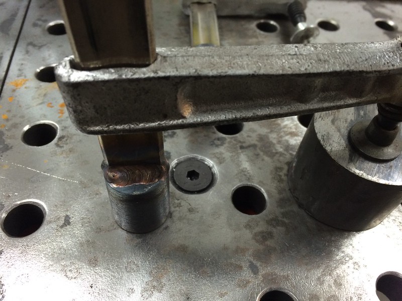
I made some clamps today. Really easy, just saw off one end and weld a pin I made on my lathe.
The pin is made from CK45 (because this is what I had available) so I used some ER312 to weld it just in case.
 Welding table by Taz00, on Flickr
 Welding table by Taz00, on Flickr
On the other hand the holes are not that far off, 0.5mm at the most which is more than adequate for my application. If I want better I can always use shims.
I made some clamps today. Really easy, just saw off one end and weld a pin I made on my lathe.
The pin is made from CK45 (because this is what I had available) so I used some ER312 to weld it just in case.
Welding table by Taz00, on FlickrWelding table by Taz00, on Flickrbalmerchris
barnacle picker
- Messages
- 611
- Location
- Co. Armagh
Excellent work there. It's always more fun to make your own version of something that costs a fortune. Don't think 0.5 mm difference in hole spacing will cause you any problems but I like your suggestion of getting one plate cnc cut and use as a template.
What sort of things are you going to be making on that bad boy?
What sort of things are you going to be making on that bad boy?
Nothing in particular.
I am a welding engineer not a welder and most of my welding is actually pipe welding. However since I decided to build a new welding table I figured I should make it the way I want it instead of making something quick and regretting it later.
I am a welding engineer not a welder and most of my welding is actually pipe welding. However since I decided to build a new welding table I figured I should make it the way I want it instead of making something quick and regretting it later.
fixerupper
Member
- Messages
- 1,684
- Location
- Crete Greece
Looks very nice , you seem to have loads of space I'm dead jealous ....jeff...
Looks can be deceiving. This is the basement of the new house I am building and will be used as a garage. After the house is finished I will not be able to use it for this type of work.
The table's final location is the one in the last photos where it is painted and it is beginning to get crowded in there.
The table's final location is the one in the last photos where it is painted and it is beginning to get crowded in there.
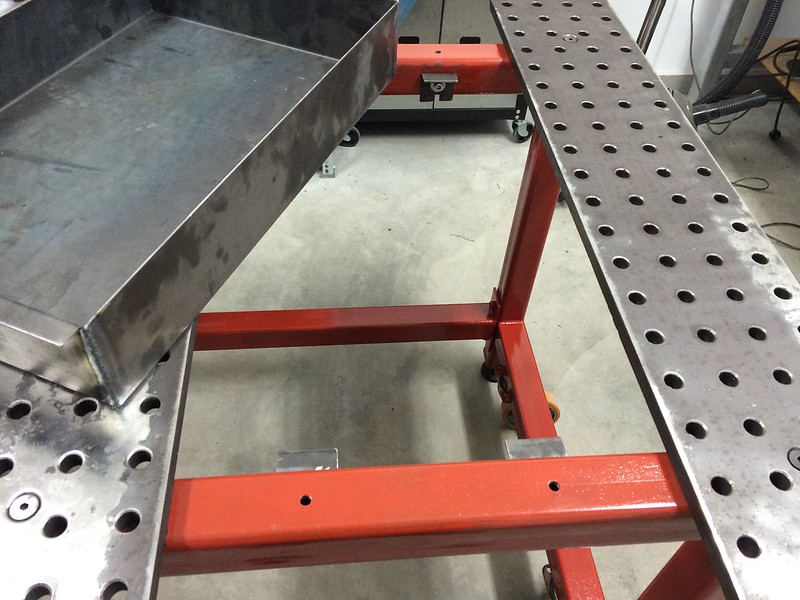
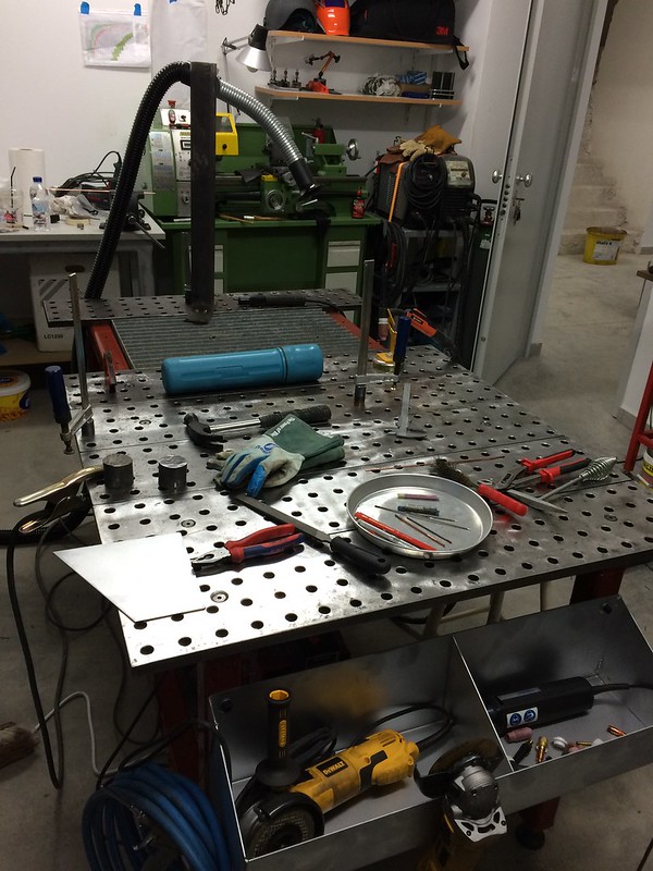
The table is finally finished. Here with accessory trays attached.
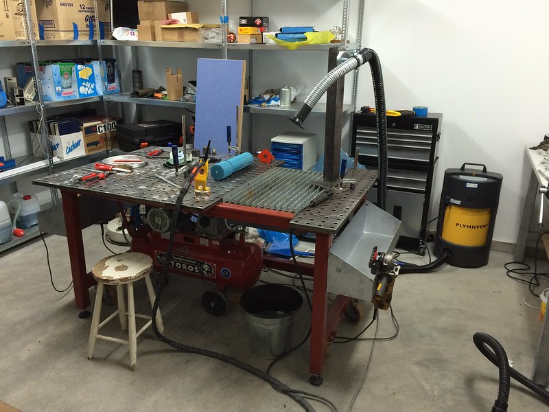 Welding table by Taz00, on Flickr
 Welding table by Taz00, on Flickr
Welding table by Taz00, on FlickrWelding table by Taz00, on Flickr 