


lorenzo
Member
- Messages
- 151
Hey guys....... just finishing up on this crane project and I wanted to share some more pics....
This phase of the fabrication is for the platform that will support the drive engine for the augers. The "spotter" which is the part that I featured before is positioned on the same side as the boom and operators cab, this is where the augers attach. The "platform" and drive engine are at the rear of the crane and the weight of the drive engine will be used as part of the counterwieght system.
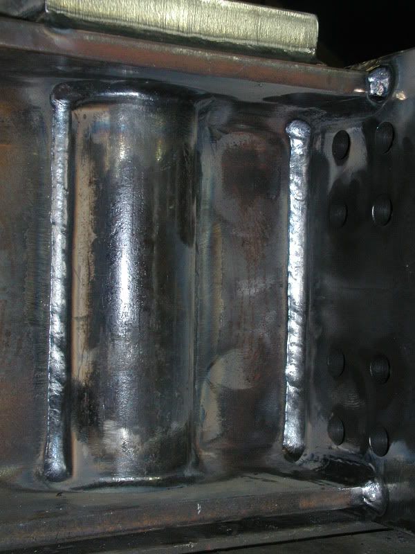
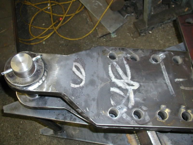
The first series of pics are of an adjustable beam. In the web of the bean are 2 tubes. These are pass through points for the Dewey Dag rod that wll be used to make adjustment to align the platform. A locking nut will be used on either side of the I beam to secure the beam after the adjustments are made.
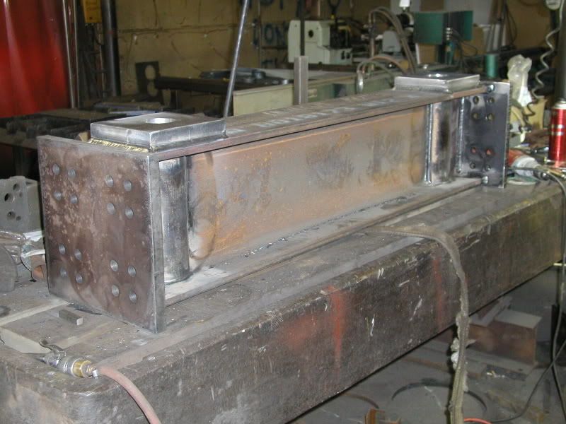
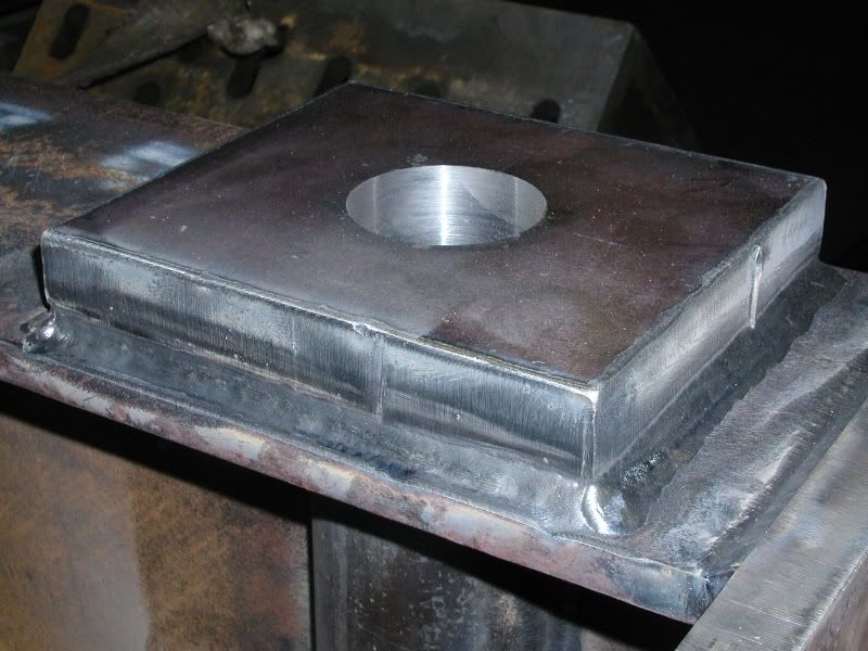
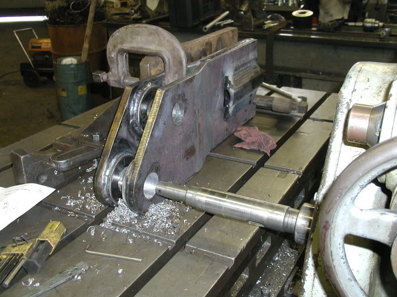
These are the ends that one end of the Dewey Dag will thread into....
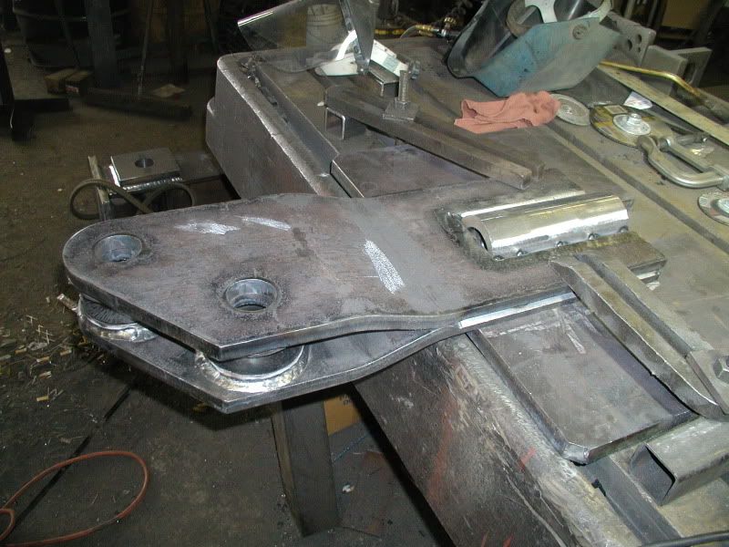
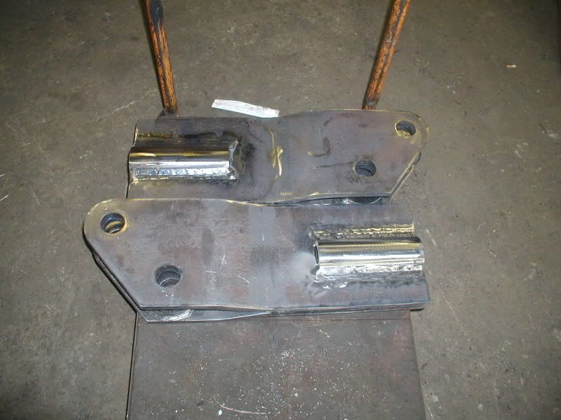
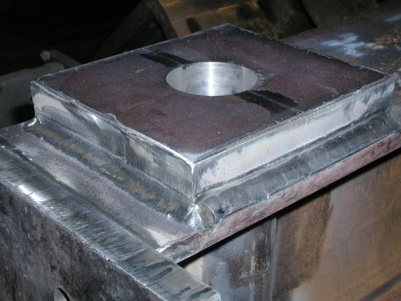
notice the size of the thread in the coupler.... the OD of the coupler is 3.5 inches approx 89 mm.
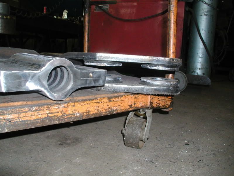
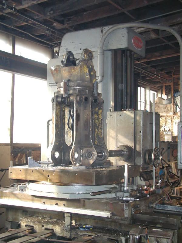
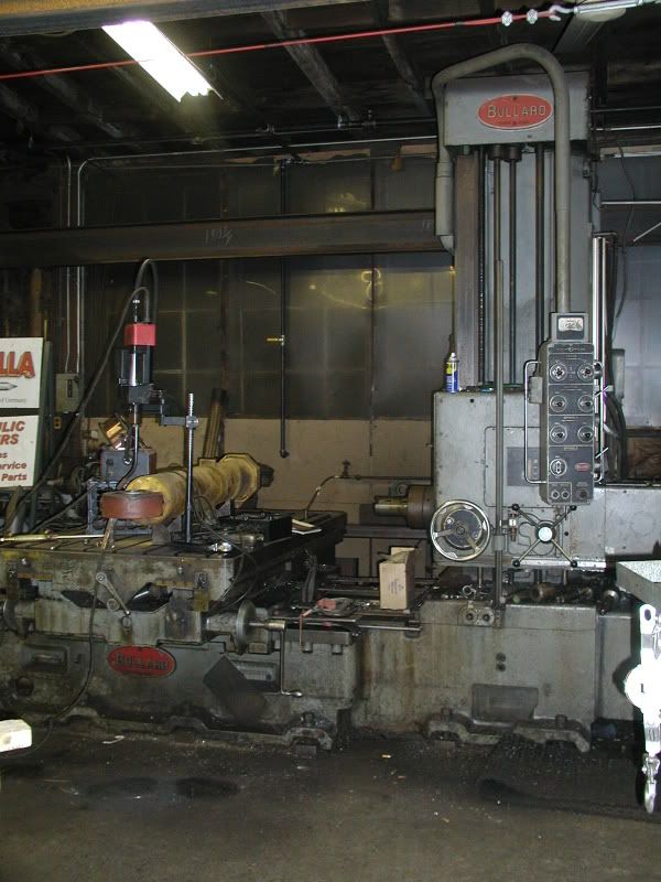
After welding it's off to the boring table....
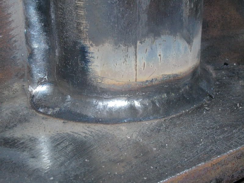
I know it's hard to draw a visual of what this stuff does exactly... hopefully I'll be able to get some pics of this stuff after it is mount and in service.
This is another component we made up....
This phase of the fabrication is for the platform that will support the drive engine for the augers. The "spotter" which is the part that I featured before is positioned on the same side as the boom and operators cab, this is where the augers attach. The "platform" and drive engine are at the rear of the crane and the weight of the drive engine will be used as part of the counterwieght system.
The first series of pics are of an adjustable beam. In the web of the bean are 2 tubes. These are pass through points for the Dewey Dag rod that wll be used to make adjustment to align the platform. A locking nut will be used on either side of the I beam to secure the beam after the adjustments are made.
These are the ends that one end of the Dewey Dag will thread into....
notice the size of the thread in the coupler.... the OD of the coupler is 3.5 inches approx 89 mm.
After welding it's off to the boring table....
I know it's hard to draw a visual of what this stuff does exactly... hopefully I'll be able to get some pics of this stuff after it is mount and in service.
This is another component we made up....
")


