Spot the welders dog
Member
- Messages
- 580
- Location
- smoggy town
I wonder if any of you could help me diagnose what may be the problem with this toy. I have been lumbered with this since January, although it has resided in the 'to do pile' for a while since.
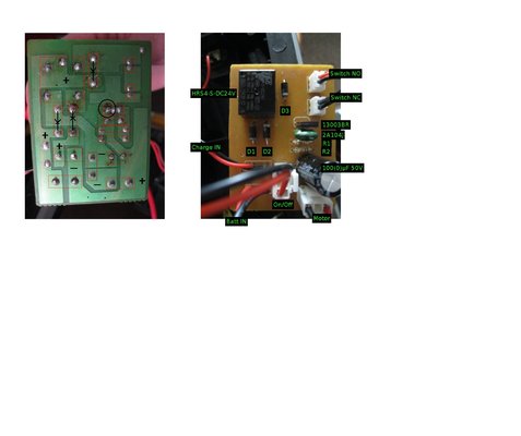
The toy is a 'Jambuster' electric scooter. The batteries are only showing 23'ish volts. I have linked the source direct to the motor which spins the wheel, so the only suspect seems to be the speed controller. I initially found a broken leg to one of the diodes, which once replaced solved nothing.
I tested what I could with limited fault finding knowledge: the relay threw when energized directly but does not throw in normal use, the switches all tested OK...
...thinking there are only a few components on the PCB it would be easier just to swap them all out to remedy a fix.


The two resistors are the only things that remain untouched. Also I boo boo'd with the cap rating which should be 1000µF.
The diode(D3) is perplexing me: Out of circuit it reads fine; in circuit it shows strange values on both poles.
To add further context. I do not believe this toy had ever worked because the wheels show no sign of use. The toy arrived to me with the PCB mis-mounted inside its holder (suspect prior fiddling).
Is it possible the circuit has been constructed incorrectly ie. How can I ascertain, without a wiring diagram, if the board was printed incorrectly thus placing the diodes '**** about face' for instance?
The 'On/Off' and 'Motor connectors are interchangeable / as are the NO and NC switches. How would I know if they are in the wrong place, and would it matter?
You can possibly tell I am out of my comfort zone here!
If anyone could give me a pointer what to try next, or a few examples of how to fault find further, that would be most appreciated.
My options seems to be:
A) Fix this board.
B) Buy a generic speed controller and force it to fit
C) Tell the child the toy had gone to heaven and add the wheels to my project pile
Love ya
The toy is a 'Jambuster' electric scooter. The batteries are only showing 23'ish volts. I have linked the source direct to the motor which spins the wheel, so the only suspect seems to be the speed controller. I initially found a broken leg to one of the diodes, which once replaced solved nothing.
I tested what I could with limited fault finding knowledge: the relay threw when energized directly but does not throw in normal use, the switches all tested OK...
...thinking there are only a few components on the PCB it would be easier just to swap them all out to remedy a fix.
The two resistors are the only things that remain untouched. Also I boo boo'd with the cap rating which should be 1000µF.
The diode(D3) is perplexing me: Out of circuit it reads fine; in circuit it shows strange values on both poles.
To add further context. I do not believe this toy had ever worked because the wheels show no sign of use. The toy arrived to me with the PCB mis-mounted inside its holder (suspect prior fiddling).
Is it possible the circuit has been constructed incorrectly ie. How can I ascertain, without a wiring diagram, if the board was printed incorrectly thus placing the diodes '**** about face' for instance?
The 'On/Off' and 'Motor connectors are interchangeable / as are the NO and NC switches. How would I know if they are in the wrong place, and would it matter?
You can possibly tell I am out of my comfort zone here!
If anyone could give me a pointer what to try next, or a few examples of how to fault find further, that would be most appreciated.
My options seems to be:
A) Fix this board.
B) Buy a generic speed controller and force it to fit
C) Tell the child the toy had gone to heaven and add the wheels to my project pile
Love ya