Hi guys, I have to make a powered fold-down bridge for car access across a gap.
In true James Bond / Batman style when 'stowed' the bridge must look like a wooden panelled fence, about 2.5m wide x 5 foot high (love the use of units there), to 'blend in'. The appearance of the rear face is less important.
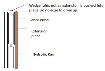
That's the easy bit. Due to the geometry of the gap, it needs a second bit to fold out as an extension to the main bridge to fill in a triangular space. See diagrams below, which i hope make sense.
Has anyone ever built anything like this?
The bridge will be lowered by an electric winch-powered steel cable. It isn't in daily use.
Does anyone have any sensible ideas about how to get the second (much lighter) part to extend at double the rate of the first bit (180 degrees, instead of 90)? I need a system that allows some angular flexibility when deployed, as the surface it rests on isn't exactly horizontal.
Any bright ideas, please shout!
Cheers, Al.
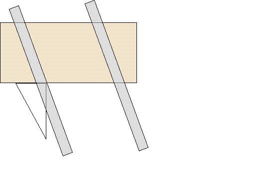
First diagram is deployed shape from above. Grey lines are car tyre tracks showing rough lines of use. The triangle is the extra bit, the main hinge line is at the top of the diagram.
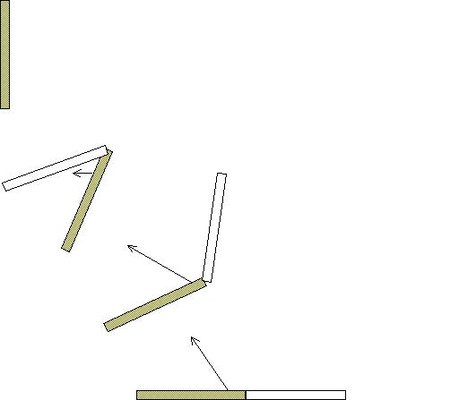
Second one shows the required deployment, unless the secondary bit can be made to slide out of the first... (Arrow is steel cable direction)
In true James Bond / Batman style when 'stowed' the bridge must look like a wooden panelled fence, about 2.5m wide x 5 foot high (love the use of units there), to 'blend in'. The appearance of the rear face is less important.
That's the easy bit. Due to the geometry of the gap, it needs a second bit to fold out as an extension to the main bridge to fill in a triangular space. See diagrams below, which i hope make sense.
Has anyone ever built anything like this?
The bridge will be lowered by an electric winch-powered steel cable. It isn't in daily use.
Does anyone have any sensible ideas about how to get the second (much lighter) part to extend at double the rate of the first bit (180 degrees, instead of 90)? I need a system that allows some angular flexibility when deployed, as the surface it rests on isn't exactly horizontal.
Any bright ideas, please shout!
Cheers, Al.
First diagram is deployed shape from above. Grey lines are car tyre tracks showing rough lines of use. The triangle is the extra bit, the main hinge line is at the top of the diagram.
Second one shows the required deployment, unless the secondary bit can be made to slide out of the first... (Arrow is steel cable direction)
")