Right, one day I'll stop asking stupid questions about motors & wiring, but until then:
Finally forked out on a new fan and speed controller. Single phase.
Motor has a starting capacitor (2 wires, obviously).
Motor has 4 wires (including earth).
Speed control has regular E, N, L inputs - ok so far - and 4 outputs - E, Z, U, U/Z.
I assume this means I use the '3 wire control' scheme on the speed controller?
I attach the label on the motor housing and the wiring diagram for the speed controller.
My question is, how do brown / blue & black on the motor relate to U, Z & U/Z outputs on the controller?
Where do I wire in the capacitor? (OK, should be obvious from the diagram once I know which wire is which).
What do the lines between L & N and between N and (blacked out circle) on the fan housing mean?
Ta for any help. I've finally forked out real money, so I know these are designed to go together.
Al.
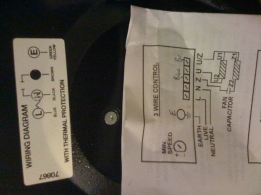