


You are using an out of date browser. It may not display this or other websites correctly.
You should upgrade or use an alternative browser.
You should upgrade or use an alternative browser.
help with repair of my euromig 260 mig welder
- Thread starter jorva
- Start date
I've finally found a bit of time to look at this again. I've got a couple of suggestions, will sort out some pictures later today
Thats great Nielj, thnx. Let me know what to do
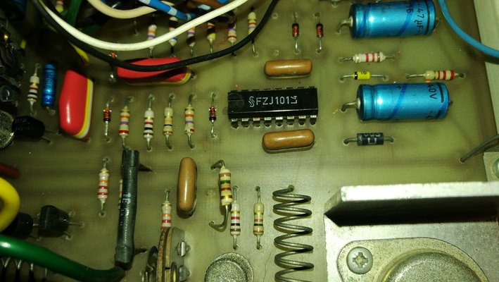
I still haven't managed to sort some pictures out but the first test I was going to suggest is to do with the FZJ101 reset input (pin 5). Can you measure the voltage between FZJ101 pin 5 (reset) and pin 8 (ground), in each of the four operating modes (normal, latched, spot and stitch) both with the trigger pressed and also with it released? So that will be 8 voltage measurements in total. I'm curious to know what is going on with that reset signal and if it's correct.
Here we go. I just measured as u asked and the reading I got are:
-4T mode (latched) = 15V without pressing trigger voltage drops to 13,5V when in latched mode. No change when pressing the trigger
-2T mode: 0V without pressing the trigger 15V when I press the trigger
-Spotweldmode: same as 4T mode, turning the timer pot does not change the voltage
Stitch weld mode: 0V without pressing the trigger, only 10V when pressing the trigger nö change when i turn the timer potentiometer.
Finally found a bit more time to look at the schematic again 
All those voltages look good and confirm that the switch wiring is correct for that side of the switch as well (white, blue, brown and green wires). In 4T mode, when you press the trigger to start welding, a pulse signal is sent to FZJ101 pin 14 (clock input) and this toggles the outputs (correctly in this case, one press of the trigger successfully starts the welding process every time). When you press the trigger a second time to stop the welding process, the same pulse signal is sent to the same FZJ101 pin 14 and this should toggle the outputs again, but this doesn't work correctly and needs multiple trigger presses to make it happen. There should be no difference in operation here because it's the same signal each time you press the trigger.
The only real difference is the FZJ101 Q output is off when you first press the trigger, but is on when you press the trigger for a second time. I've therefore had a good look at the schematic to see if there is any way the Q output could be interfering with the clock input and there is a feedback loop via the timer circuit. For this feedback loop to interfere with the second trigger press there must be some sort of fault within the timer part of the circuit, which may not be easy to find. However, if my theory is correct, removing / disabling this loop should make the 4T mode operate correctly.
To test this theory you would need to remove a diode from near the centre of the board as circled in red below, this will disconnect the timer circuit trigger signal going to FZJ101 pin 14.


There is no need to check any other modes with the diode removed, just try the 4T mode and see if it stops welding correctly on the second trigger press.
All those voltages look good and confirm that the switch wiring is correct for that side of the switch as well (white, blue, brown and green wires). In 4T mode, when you press the trigger to start welding, a pulse signal is sent to FZJ101 pin 14 (clock input) and this toggles the outputs (correctly in this case, one press of the trigger successfully starts the welding process every time). When you press the trigger a second time to stop the welding process, the same pulse signal is sent to the same FZJ101 pin 14 and this should toggle the outputs again, but this doesn't work correctly and needs multiple trigger presses to make it happen. There should be no difference in operation here because it's the same signal each time you press the trigger.
The only real difference is the FZJ101 Q output is off when you first press the trigger, but is on when you press the trigger for a second time. I've therefore had a good look at the schematic to see if there is any way the Q output could be interfering with the clock input and there is a feedback loop via the timer circuit. For this feedback loop to interfere with the second trigger press there must be some sort of fault within the timer part of the circuit, which may not be easy to find. However, if my theory is correct, removing / disabling this loop should make the 4T mode operate correctly.
To test this theory you would need to remove a diode from near the centre of the board as circled in red below, this will disconnect the timer circuit trigger signal going to FZJ101 pin 14.
There is no need to check any other modes with the diode removed, just try the 4T mode and see if it stops welding correctly on the second trigger press.
Thnx again Niel.
I wil try this however, i just read your post. And (think) i wrote my explanation a bit wrong in one of my previous posts doing measuremens in spot weld mode. 2T mode and 4T both work like they shoud.
2T mode: starts welding when pressing the trigger and stops when releasing it.
4T mode press trigger goes in to latched mode and keeps welding until you press the trigger again.
So those 2 seem to be ok.
Then for spot weld and stitch weld mode
Spot weld mode: Press the trigger (goes into latched mode) starts welding and keeps on welding, timer potentiometer has no influence. It does not come out of lathched mode until you press the trigger multiple times.
Stitch welding: goes into latched mode keeps on welding does not stop or start by it self like it schoud do for stitch welding. To get it out of this mode i need to press the trigger multiple times.
I wil try to make a video this weekend of what it does in each mode. so you can see what i does in each mode.
Ok, in that case try removing the diode as suggested but try all modes as follows:
4T: this should still work as normal, as it did before you removed the diode.
2T: this should also still work as normal.
Spot weld: this should now behave exactly the same as the 4T mode
Stitch mode: this should now behave exactly the same at the 2T mode
Try that and let me know what happens.
4T: this should still work as normal, as it did before you removed the diode.
2T: this should also still work as normal.
Spot weld: this should now behave exactly the same as the 4T mode
Stitch mode: this should now behave exactly the same at the 2T mode
Try that and let me know what happens.
I removed the diode, and it exactly does like you said spot weld mode acts like it is in 4T mode. Press the trigger it starts, let it go it stops.
And stitch mode like it is 2T mode press trigger once starts, press it again it stops.
So 2T and 4T mode both are ok and working like they shoud.
And stitch mode like it is 2T mode press trigger once starts, press it again it stops.
So 2T and 4T mode both are ok and working like they shoud.
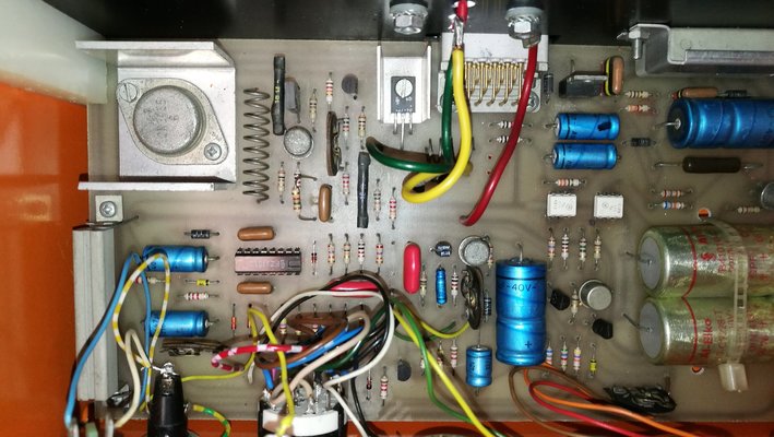
Ok, that suggests the fault that is stopping the spot and stitch modes working correctly is something to do with the timer circuit that you have now disabled by removing the diode. Your pcb is not quite the same as the schematic so the first thing I'll need to do is sketch out your schematic from the photo's (I was going to do this a few months ago but never got chance to!). Have you replaced all the diodes and also the BRY56 on the board or are some still the originals?
Ok so the fault is in the timer circuit. I am curious to find what it is. Yes you explaind that couple posts ago that there was som difference and my pcb does not have 2 timers for the stitch welding.
Take your time im not in a hury and i am glad that you want to have a look in to al of this.
Then for the diodes, do you mean like the one i took of today? Or do you mean al of what is on the pcb? I have not replaced al those (orang-black) diodes but i did measure them and they al had about the same values. But if you think one of those coud b the problem i woud not mind replacing the old ones with new ones.
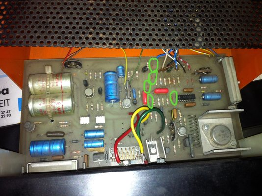
The other two on the front of the pcb (circled in red) plus the one on the back linking across the blue/white and red/white wires are also part of the timer circuit. Try changing those three out as well for a start and see if that cures the fault.

That's interesting and seems to suggest there was something faulty with one of the old diodes. The fact that the timer is now not working but is also not interfering with the trigger is an improvement I think. The remaining 'fault' might just be that the BRY56 is not triggering because the 4k7 preset is not set correctly. Try adjusting the preset in both directions and see if you can get the spot & stitch modes to do something, preset is the middle of the pcb circled in red:

If that doesn't work then we're back to measuring some of the voltages again with your multimeter to see what's happening around the timer circuit.
Try the preset first and let me know if anything happens
If that doesn't work then we're back to measuring some of the voltages again with your multimeter to see what's happening around the timer circuit.
Try the preset first and let me know if anything happens
I adjusted the preset and yes we now have a functioning timer in spotweld mode however I think there is something wrong with the preset need to have a closer look at it.
And an other strange thing the timer works in spot weld mode but not in stitch mode
however I think there is something wrong with the preset need to have a closer look at it.And an other strange thing the timer works in spot weld mode but not in stitch mode
Ok so timer is also working in stitch mode now i just did not know how this worked and I had the wire feed at its lowest setting.
One more question. How is this stitch mode supposed to work? When I put it in stitch mode now it starts welding and then the wire feed stops. does it need to come on by it self again?
One more question. How is this stitch mode supposed to work? When I put it in stitch mode now it starts welding and then the wire feed stops. does it need to come on by it self again?
Ok getting smarter by the minute. The burn back potentiometer is the adjustment for the second timer of the stitch welding function however I can not realy adjust the time witch is between welds. If I adjust it to 1 on the scale it Wil stop and start welding on its own. But I can only adjust how long it welds with the actual timer that is also used for the spot weld function. Is the preset in the lower left of the pcb for the burnback/ stitch of timer?
I think we can say we now have a almost fully functioning mig welder.
however I can not realy adjust the time witch is between welds. If I adjust it to 1 on the scale it Wil stop and start welding on its own. But I can only adjust how long it welds with the actual timer that is also used for the spot weld function. Is the preset in the lower left of the pcb for the burnback/ stitch of timer?I think we can say we now have a almost fully functioning mig welder.
Last edited:


