Bad luck with the soldering iron
Here's what I think with the wiring:

I've had to zoom in a bit which gives poor resolution bur hopefully you can see everything.
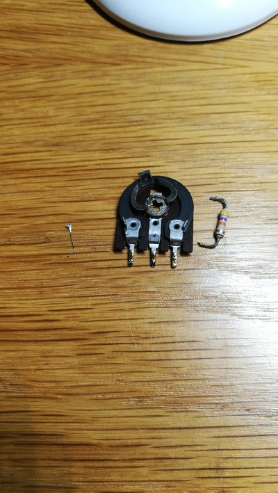
The switch is what's called a 3 pole 4 way rotary switch, in your case you're only using two of the poles (pins C and 9 to 12 are not used). The first pole is pins A and 1 to 4, the second pole is B and 5 to 8. A will connect to 1,2,3 or 4 depending on the switch position and B will connect to 5,6,7 or 8. There is no electrical connection between A and B so on a schematic it can look like two separate switches (as above).
On the schematic above, I've numbered the pins and also added what I think the colours should be. Pin 1 might look a bit black but it's brown.
So my thinking is as follows:
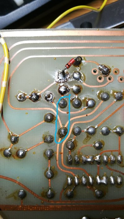
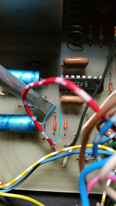
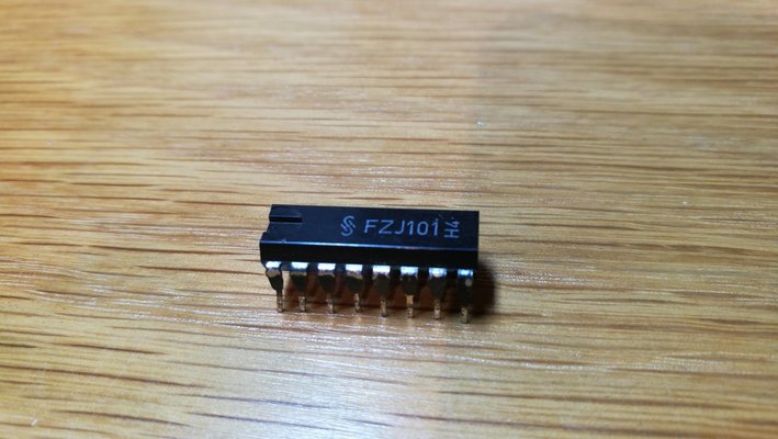
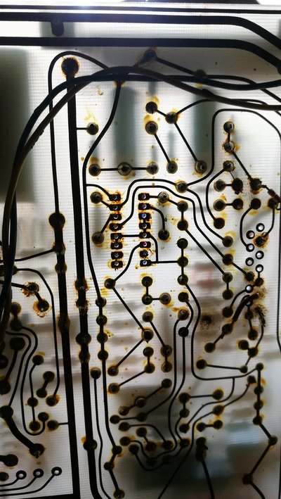
We know the 1k8 resistor that you measured yesterday ends up at the blue wire, so we know terminal 2 must be part of the switch on the left of the FZJ101. That means that part of the switch must be pins A and 1 to 4. We can also see the link there between 1 and 3 (there is no corresponding link on the right side part of the switch). We also know that the green wire ends up at FZJ101 pin 5 and also connects to the 27k resistor you can see going up to the +15v rail (27k is red, violet, orange, gold). So the green wire must go onto switch terminal A.
That means by default that the black wire should go on switch terminal B but we can check this as well. If you follow the black wire connection on the PCB you will see it ends up at a resistor with colours blue, grey, orange and gold, which is 68k. On the schematic you can see there is a 68k resistor just to the right of the right part of the switch, which confirms that's correct. As you say, the speed pot white and black wires are closely associated with the blue / white and red / white wires from the switch. On the schematic above I've highlighted the speed pot and as you can see it is associated with the blue / white and red / white wires.
Two things to note from above:
The schematic shows wires on switch pins 5 and 6 which you don't have. The old switch also didn't have wires on pins 5 and 6 (no solder on pins). There are also no soldered connections on the PCB around the switch wiring that do not have wires connected so I can't see any evidence of wires being removed. This is obviously a difference but I wouldn't worry about this for now, maybe the schematic is not 100% correct for your unit.
Secondly, the speed pot above might look like it's connected to switch pins 7 and 8 but it's just a resolution issue, the speed pot (white wire) only goes to switch terminal 7 (blue / white).
Here's what I think with the wiring:
I've had to zoom in a bit which gives poor resolution bur hopefully you can see everything.
The switch is what's called a 3 pole 4 way rotary switch, in your case you're only using two of the poles (pins C and 9 to 12 are not used). The first pole is pins A and 1 to 4, the second pole is B and 5 to 8. A will connect to 1,2,3 or 4 depending on the switch position and B will connect to 5,6,7 or 8. There is no electrical connection between A and B so on a schematic it can look like two separate switches (as above).
On the schematic above, I've numbered the pins and also added what I think the colours should be. Pin 1 might look a bit black but it's brown.
So my thinking is as follows:
We know the 1k8 resistor that you measured yesterday ends up at the blue wire, so we know terminal 2 must be part of the switch on the left of the FZJ101. That means that part of the switch must be pins A and 1 to 4. We can also see the link there between 1 and 3 (there is no corresponding link on the right side part of the switch). We also know that the green wire ends up at FZJ101 pin 5 and also connects to the 27k resistor you can see going up to the +15v rail (27k is red, violet, orange, gold). So the green wire must go onto switch terminal A.
That means by default that the black wire should go on switch terminal B but we can check this as well. If you follow the black wire connection on the PCB you will see it ends up at a resistor with colours blue, grey, orange and gold, which is 68k. On the schematic you can see there is a 68k resistor just to the right of the right part of the switch, which confirms that's correct. As you say, the speed pot white and black wires are closely associated with the blue / white and red / white wires from the switch. On the schematic above I've highlighted the speed pot and as you can see it is associated with the blue / white and red / white wires.
Two things to note from above:
The schematic shows wires on switch pins 5 and 6 which you don't have. The old switch also didn't have wires on pins 5 and 6 (no solder on pins). There are also no soldered connections on the PCB around the switch wiring that do not have wires connected so I can't see any evidence of wires being removed. This is obviously a difference but I wouldn't worry about this for now, maybe the schematic is not 100% correct for your unit.
Secondly, the speed pot above might look like it's connected to switch pins 7 and 8 but it's just a resolution issue, the speed pot (white wire) only goes to switch terminal 7 (blue / white).