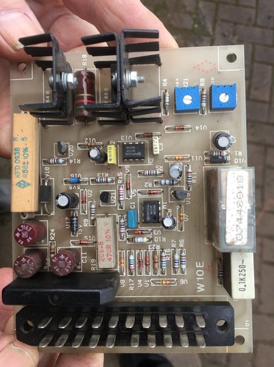
Have retired and want to do a bit of welding Got given a Murex Tradesmig 251 but it has a problem with the wire feed Have a bit of experience with electronics and have traced the fault to the PCB 
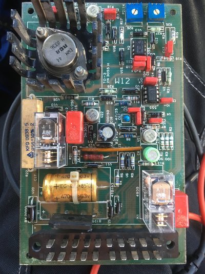
All pots and switches are OK and I have power to the PCB Contactor clicks but no feed Motor is OK Has anyone a circuit diagram for this PCB ??? Thanks in advance JR
hi try trace motor feed to a transistor as a varible voltage sorce or a pwr circut the motor is vary speed thanks
http://www.murexwelding.co.uk/manuals/other/Instruction Manuals/Tradesmig 191-251-253-293.pdf wiring diagram is near the bottom of manual if that helps
Have checked ALL components and tracks on the PCB All OK If I can get a circuit diagram I am sure I can make it work Have tried Murex they do not seem interested Found a cschematic for the welder but cannot find anything for the PCB Thanks for taking the time to reply JR
Thanks have already found the welder diagrams but cannot see anything for the PCB If I cannot get diagram for PCB will have to rig up test circuit on my bench and then spend some time with meter and scope Hope to save a lot of time with a diagram JR
I was looking for murex info a little while ago, came across numerous posts looking for detailed circuit diagrams, seems like they on a par with the current availability of multicoloured unicorn poo.
I think hens teeth are just a little more common I will probably spend some time drawing out the circuits if I cannot get a drawing If so I will post it JR
Above is a photo of the PCB in my Eland 175 MIG. It's a different machine, made in Hungary, but I think the original design was by Murex, and so they may share the same PCB. It has variable Spot and Stitch timers. The board has a bridge rectifier, a couple of 555 timers, and two LM324 quad op-amps. The two TO-220 transistors with heatsinks are an IRF530 and IRF9530 MOSFET pair. They drive the wirefeed motor, maybe with PWM control, and maybe one of them is a brake ( to stop the wirefeed instantly when the torch trigger is released ). I can access the board in-situ when under power, and measure voltages and view signals, so if the board is similar to yours and you want me to check something, let me know.
Thanks for the offer This board does look very similar except for the position of the relay etc The two TO-220 transistors on the heat sink are the same I have checked these and also replaced them and checked all components and external pots etc By accident whilst working on it I noticed that with the trigger taped on and the board was twisted the motor would pulse so PCB is now back on the bench for a detailled examination and I will solder every connection could be a dry joint !!! Watch this space JR
Thanks for all offers of help went over PCB and soldered EVERY connection whether it looked good or bad Hey presto up and running JR
Hi Everyone, my name is Paul from Northern Ireland. I am new here. I am hoping someone can help me. I’ve got a Murex 251 trademig that won’t feed. I have another PCB installed (a W10E although slightly different from my PCB) that I borrowed from a friend and I can confirm the feed motor is working 100%. I’ve attached a picture of my faulty PCB board. It’s a W12. I was wondering, when I do a continuity test between pins A7 and B9 I get a short. If someone who has the same board could maybe confirm if this is reading is supposed to be the case. On the W10E these pins are not shorted which leads me to believe I have a problem. I changed the relays but fault is still there. I’ve tested all components on the board and all seems ok. I’ve resoldered any suspicious solder joints. Still on joy. The picture of the W10E is my friends PCB that I borrowed just to test the welder and motor was all ok. Any help would be very much appreciated. many thanks in advance Paul
Hello Paul, and welcome to the Forum ! I have an Eland 175 MIG, which is based on a Murex design, and the Control PCB is similar. From my photo in Post #10, it looks like my PCB is like a W10E. I do not have, and have never seen, a circuit diagram for the PCB, but from the general circuit diagram for a Murex, the pins A7 and B9 on the multi-pin connector at the PCB are the connections that go to the wirefeed motor. In my Post #10, I was guessing that the two TO-220 semiconductors with heatsinks ( MOSFETs ) are the driver and the brake for the wirefeed motor. The brake will be turned on ( conducting ) by the control logic when the torch trigger is released, and this will short the motor armature and cause it to stop dead. On your W12 board there is only one TO-3 power transistor on a heatsink. I guess that this is the motor driver. The brake function is probably accomplished by a normally-closed ( NC ) pair of contacts on one of the two relays. In the "rest" position, with the torch trigger released, these contacts will short the motor, to brake it. I think this is the short-circuit that you are measuring between pins A7 and B9. So yes, this short is normal. What isn't normal is that when you press the torch trigger, that relay should operate, removing the armature short and instead connecting the motor to the variable-speed driver transistor. It is possible that when you press the trigger, one of the relays does operate, and it may feed the main Contactor which runs the welding transformer, and maybe also the gas valve. However, I guess that both relays should operate, and one of them is not doing so? You have changed both relays, so there must be a fault in the control logic. That has timers, integrated circuits, and small driver transistors. The logic on that board, from the torch trigger switch to the relay, has to be debugged - without a circuit diagram...!!..., or the PCB replaced. Can you troubleshoot the board, or get someone local to do it? One option would be for you to send the W12 PCB to me, and I would try to debug it in my Eland welder.
These machines were produced in Hongerian and bought by Murex. ESAB has nothing to do with this item.
Thanks for your reply guys. Apologies for my very late reply. I just couldn’t get around to dealing with this with one thing and another. Eddie49, thanks for confirming the details in the operation of the circuit and of the short I was measuring. And for offering to have a look at it. So Much appreciated. I continued by removing all the transistors from the circuit and testing them all individually on my transistor tester and found v23 2N3019 to be at fault. I thought I had checked this on my multimeter on diode setting but I guess I overlooked the fact that two pins where open. I ordered a replacement and replaced it and tested it in the welder. All now working 100%. Im delighted. Again thanks to all who took time to reply.