mike 109444
Member
- Messages
- 4,873
Think xmetal has a point on the dry solder joints. Worth running a hot iron over any that look a bit iffy.
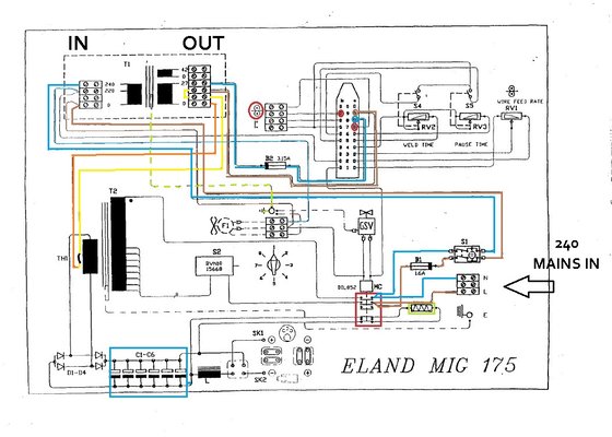
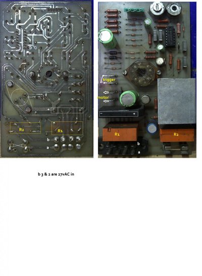
The attached pic is what I have been working out from the info so far. The reason I though the 27vAC was switched is it looks to be on the 175 so another difference!
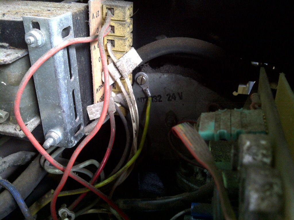
So as the 27vAC is always ON feed to the pcb then if you look at the pic and meter on the + and - of the black oblong (it's a bridge rectifier, AC in and DC out) so set meter to DC and see if there is aprox 20 to 30v DC on those pins, after you have reflowed the solder that is.
Are the two relays (R1 and R2) the same, do they have same number on them ? If they are a quick and cheep trick would be to desolder and swap them around. This should at the very least change the fault and MAY get some of the functions working.
The attached pic is what I have been working out from the info so far. The reason I though the 27vAC was switched is it looks to be on the 175 so another difference!
So as the 27vAC is always ON feed to the pcb then if you look at the pic and meter on the + and - of the black oblong (it's a bridge rectifier, AC in and DC out) so set meter to DC and see if there is aprox 20 to 30v DC on those pins, after you have reflowed the solder that is.
Are the two relays (R1 and R2) the same, do they have same number on them ? If they are a quick and cheep trick would be to desolder and swap them around. This should at the very least change the fault and MAY get some of the functions working.


 I should have it soldered in place by the middle of next week.
")