


You are using an out of date browser. It may not display this or other websites correctly.
You should upgrade or use an alternative browser.
You should upgrade or use an alternative browser.
Elektra Beckum Typ- CO2 120/15
- Thread starter bloobloo
- Start date
I'm amazed that no-one has suggested testing each diode individually - I must have changed half a dozen or more over the years on my murex 130. Check your
Deffo worth checking, but if one had failed wouldn't it cause a short and be blowing fuses e
bloobloo
Professional Tinkerer
- Messages
- 271
- Location
- Ashton in Makerfield, Wigan UK
bloobloo
Professional Tinkerer
- Messages
- 271
- Location
- Ashton in Makerfield, Wigan UK
Thread resurrection! I think I may have blown something........ yesterday the welder was working - not brilliantly but working. So I thought I would change the wire speed pot again (it still had the 10k x10 turn one in that worked) I tried a few different pots in there from 5k to 50k and none of them worked, the wire speed was just constant no matter where the pot was turned to.
So, as it was getting late last night i thought i would just put the 10 turn pot back in. however upon doing so, there is now no power going to the wire feed motor either with or without the pot connected...
So i tried connecting the wire feed motor to my drill battery to test it and it turns just fine. I then tested for voltage to the motor and nothing at all.
What have I done!
bloobloo
Professional Tinkerer
- Messages
- 271
- Location
- Ashton in Makerfield, Wigan UK
-Yeah, earth clamp is negative and tip is positive.BTW did anyone check polarity of the gun & work leads ?
Might have been switched for Flux core.
Looking over this thread, you've had wire speed issues right from the start.
It should be a fairly reliable circuit, since the photos in Post #11 show a pretty simple wire speed control board with few components. The small chip is probably an NE555 timer, sending pulse-width modulated ( PWM ) control pulses to the large diamond-shaped ( TO-3 outline ) power transistor on the heatsink, which drives the motor. Something has failed and these pulses are no longer present. To check and fix this, it may be necessary to reverse-engineer some of the circuit ( by looking at the component-side and track-side of the board ), and using an oscilloscope.
However, start by checking the power source for the motor - which is actually the DC welding voltage itself. This machine does not have an independent ( auxiliary ) motor supply, it borrows the welder output. So check if the wirefeed motor fails to run at all settings of the main rotary voltage selector switch, and confirm that arc voltage ( 20 to 25v DC ) is present.
bloobloo
Professional Tinkerer
- Messages
- 271
- Location
- Ashton in Makerfield, Wigan UK
I will check again in the morning, but I'm almost sure that I was getting between 18 & 24v at the tip even though the motor wasn't turning. I checked the grey transformer and thats reducing 240 v ac down to 36v ac. I'm getting no DC voltage to the motor at allLooking over this thread, you've had wire speed issues right from the start.
It should be a fairly reliable circuit, since the photos in Post #11 show a pretty simple wire speed control board with few components. The small chip is probably an NE555 timer, sending pulse-width modulated ( PWM ) control pulses to the large diamond-shaped ( TO-3 outline ) power transistor on the heatsink, which drives the motor. Something has failed and these pulses are no longer present. To check and fix this, it may be necessary to reverse-engineer some of the circuit ( by looking at the component-side and track-side of the board ), and using an oscilloscope.
However, start by checking the power source for the motor - which is actually the DC welding voltage itself. This machine does not have an independent ( auxiliary ) motor supply, it borrows the welder output. So check if the wirefeed motor fails to run at all settings of the main rotary voltage selector switch, and confirm that arc voltage ( 20 to 25v DC ) is present.
As with many MIGs of this level, the small PCB-mounted transformer is only there to operate the power-up relay via the torch trigger switch.
I have found a picture of the PCB on eBay Austria:
 It shows that the board has an NE555 timer, a small transistor in a TO-5 can, and an MJ2955 60v 15A PNP power transistor.
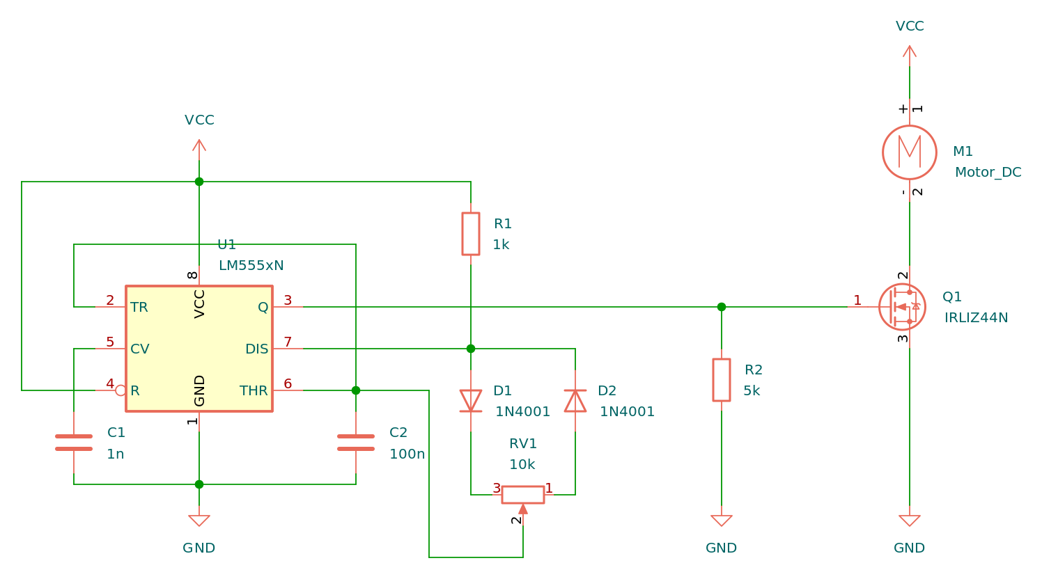
As this example circuit diagram shows:
 www.build-electronic-circuits.com
using a 10k pot to control the 555 timer chip is normal.
www.build-electronic-circuits.com
using a 10k pot to control the 555 timer chip is normal.
Regarding the welding problems with voltage positions other than 4 - perhaps the contacts on the non-enclosed rotary switch are not conducting fully at high current. You could check them visually, clean them, check the resistance across them, or bypass them ( assuming it is a simple 1-pole 4-way switch ).
I have found a picture of the PCB on eBay Austria:
REPARATUR Platine Elektra Beckum Schweißgeräte Trafo-Geräte #F06 | eBay
REPARATUR Platine Elektra Beckum Schweißgeräte Trafo-Geräte #F06 | Business & Industrie, Elektronik & Messtechnik, Relais | eBay!
www.ebay.at
As this example circuit diagram shows:
A Simple 555 PWM Circuit with Motor Example
In this tutorial, you'll learn how to build a 555 PWM Circuit. And you'll see how you can use this to control the speed of a motor.
Regarding the welding problems with voltage positions other than 4 - perhaps the contacts on the non-enclosed rotary switch are not conducting fully at high current. You could check them visually, clean them, check the resistance across them, or bypass them ( assuming it is a simple 1-pole 4-way switch ).
bloobloo
Professional Tinkerer
- Messages
- 271
- Location
- Ashton in Makerfield, Wigan UK
I did clean the rotary switch when I got it, so that's all good.As with many MIGs of this level, the small PCB-mounted transformer is only there to operate the power-up relay via the torch trigger switch.
I have found a picture of the PCB on eBay Austria:
It shows that the board has an NE555 timer, a small transistor in a TO-5 can, and an MJ2955 60v 15A PNP power transistor.REPARATUR Platine Elektra Beckum Schweißgeräte Trafo-Geräte #F06 | eBay
REPARATUR Platine Elektra Beckum Schweißgeräte Trafo-Geräte #F06 | Business & Industrie, Elektronik & Messtechnik, Relais | eBay!www.ebay.at
As this example circuit diagram shows:
using a 10k pot to control the 555 timer chip is normal.A Simple 555 PWM Circuit with Motor Example
In this tutorial, you'll learn how to build a 555 PWM Circuit. And you'll see how you can use this to control the speed of a motor.
Regarding the welding problems with voltage positions other than 4 - perhaps the contacts on the non-enclosed rotary switch are not conducting fully at high current. You could check them visually, clean them, check the resistance across them, or bypass them ( assuming it is a simple 1-pole 4-way switch ).
So could I just get a PWM motor controller from amazon / ebay etc and use that instead of the wire speed pot?
Yes, a speed controller such as:
could be used to run the wirefeed motor. The original PCB would still be required, to provide the On/Off functionality using the small transformer and the relay. We would have to trace the wires to & from the original board to work out how to add the new one.
When PWM controllers are added to machines like this, a separate stabilised DC supply ( e.g. a 21v laptop supply ) is sometimes also used to supply the motor and the new board. This is done to avoid hesitation and variation in the wirespeed due to sharing the arc voltage.
The motor can also be wired to the output of the new PWM controller using a double-pole double-throw ( DPDT ) relay, which allows for shorting the motor when idle, preventing spool run-on and excessive wire stickout.
bloobloo
Professional Tinkerer
- Messages
- 271
- Location
- Ashton in Makerfield, Wigan UK
Well, fingers crossed! 2 of those controllers will be here tomorrow from Amazon.Yes, a speed controller such as:
could be used to run the wirefeed motor. The original PCB would still be required, to provide the On/Off functionality using the small transformer and the relay. We would have to trace the wires to & from the original board to work out how to add the new one.
When PWM controllers are added to machines like this, a separate stabilised DC supply ( e.g. a 21v laptop supply ) is sometimes also used to supply the motor and the new board. This is done to avoid hesitation and variation in the wirespeed due to sharing the arc voltage.
The motor can also be wired to the output of the new PWM controller using a double-pole double-throw ( DPDT ) relay, which allows for shorting the motor when idle, preventing spool run-on and excessive wire stickout.
I may have a couple of old laptop psu bricks that I could repurpose for this too.
bloobloo
Professional Tinkerer
- Messages
- 271
- Location
- Ashton in Makerfield, Wigan UK
Well, had time tonight to have a little look at the welder again. The PWM came and I found an old laptop PSU. I tried the PWM direct to the motor and it works very well , lovely and smooth.
The next step is figuring out how to integrate the PWM into the machine and get it to work. there is 36v going to the trigger,(brown wires) No voltage at all going to the wire feed motor. The welder clunks / clicks when the trigger is pressed and I have between 18 and 23v at the tip depending on what the setting the rotary is set to.
So how can I now get the wirefeed to turn - using the PWM - or should I connect the PWM to the 36v and then run 2 new wires to the wire feed? Hope my ramblings make sense!
bloobloo
Professional Tinkerer
- Messages
- 271
- Location
- Ashton in Makerfield, Wigan UK
Ok, a little progress. I didn't use the 36v as when the trigger is pressed, it changes to 0v. the 2 spade connectors nezt to the wire feed spades show 24v when the trigger is pressed so I used those to power the PWM. Then connected the output from the PWM to the wire feed wires.. Et Voila- it works.... of a fashion, crap penetration even on the highest setting, very jittery and bouncy when welding even though the wire speed is working.
The small 36v transformer on the PCB is only rated at a couple of Watts, but the wirefeed motor needs about 50 Watts. The 36v AC will be rectified to DC - probably by the 4 diodes located between the transformer and the power transistor - and is only used to power the relay. The 36v on the brown wires going to the torch drops to zero when the trigger is pressed because that is the switch contact closing. ( The voltage across an open switch is the supply voltage; when a switch is closed the voltage across it drops to zero.)
Power for the wirefeed motor is taken from the main welding output. There are probably two thin wires - maybe red and black - attached to the heavy bolted connections at the main rectifier output, and connecting to the wire speed control portion of the PCB.
The On/Off function of the PCB will remain the same as it was: AC mains power in to run the 36v transformer, a switched AC feed from the relay contacts to the large transformer, and the two wires to the torch trigger.
As you have found, the wirefeed speed control part of the PCB can be swapped-out for the new PWM speed controller by moving 4 wires - the two going to the motor, and the two wires for the DC input power from the large rectifier.
Even on welders that work perfectly, there can be fluctuations in the wire speed if the motor runs off the arc power. As I mentioned, this can be avoided by feeding the new PWM controller from a stabilised supply, of about 20 to 24 volts DC.
The usual method would be to connect AC to the new supply as soon as the welder is powered on, and join the output of that supply to the input of the new PWM board. The board will then be ready to drive the motor at the pre-adjusted speed as soon as the torch trigger is pressed. This is done by adding another small relay, with the operating coil in parallel with the existing relay on the original PCB. So when the torch trigger is pressed, both relays will operate together.
The two moving poles of the new relay connect to the motor. The two normally-closed contacts are joined by a link wire which shorts the motor when stopping to prevent run-on of the MIG spool. The two normally-open relay contacts are connected to the output of the PWM speed controller. If you decide to do this, start by checking the coil voltage of the existing relay ( possibly 24v ? ).
However, apart from the wirefeed issues, there seems to be problems with the arc too. To investigate the lack of penetration, I would suggest checking all connections again between components in the high-current output path - the transformer secondary, the 4 rectifier connections, the inductor, the torch cable, and the work return cable and clamp.
Last edited:
bloobloo
Professional Tinkerer
- Messages
- 271
- Location
- Ashton in Makerfield, Wigan UK
Thanks for the reply Eddie, I am no where near as well versed as you are when it comes to the black art of electronics!
I was looking at the rotary switch earlier. Something struck me as unusual with it, looking at it from the rear, the left side has 240v live to the 1st pin, 2nd pin is 240 neutral and 3rd pin is a black wire to the top of the on off switch.
240v neutral is attached to the thermo glued to the side of the transformer. piggy backed off the 240 is the PSU for the fans but before the power on / off switch so that the fans run as soon as it is plugged in. Surely, the 240 *should go to the power switch first?
Yes, the 3-core AC mains input cable would normally go through the case with a strain-relief grommet and then directly to the main on-off switch. If that switch is double-pole it would control both Live ( brown ) and Neutral ( blue ). If it is a single-pole switch, it would normally be in the Live path. From there, both Live and Neutral have to go to the small "36v" transformer on the PCB.
The primary of the large transformer gets AC mains via the relay on the PCB and via the 4-way rotary power selector switch. The relay contacts may be on one side of that mains feed for the transformer ( for example, the Live ), and the rotary switch may be on the other side ( the Neutral ).
The most common arrangement for the transformer primary winding would be that one side of the mains goes to the "start" and at the other end of the primary there are four tappings, which go to the four contacts of the 1-pole 4-way rotary switch. The pole of that switch then provides the other side of the mains.
To verify that this is the actual mains wiring on your machine, that it is correct, in good condition and adequately-sized, you would need to cut cable ties, trace the wires, make a sketch on paper, note wire colours, tie on labels, etc.
During welding, the primary circuit has to supply a couple of kilowatts, so wire sizes and good tight connections do matter.
The thermal cutout should not be in the AC supply path to the main transformer! It can be in the AC supply path to the small 36v transformer on the PCB, so that if the cutout opened it would cut the mains to that transformer and the relay would drop out.
As you trace and verify this wiring it may be helpful to know that the resistance of the large transformer primary is very low - e.g. 2 Ohms or less. From the "start" of the primary ( i.e. the end where the rotary switch is not connected ) to the "most distant" end it could be 2 Ohms, and then each of the three remaining tapping points will have a lower resistance, e.g. 1.8 Ohms, 1.6 Ohms, 1.4 Ohms. The most distant end, with the largest number of winding turns, will be the lowest power setting, so should go to the Position "1" contact on the rotary switch ( which gives about 20 volts output ).
Doing all this work on the primary side, and verifying good connections on the low-voltage high-current secondary side may even solve the poor penetration issue....


