Hi all,
New to the forum and have read a few posts with interest regarding building your own tig pedal, which is something I'm embarking on.
I understand the concept. A potentiometer varies voltage which is sent as feedback to the PCB inside the welder and a microswitch turns the torch on.
The problem I'm having is figuring out how to wire everything to the 7pin plug on my TIG machine
I have a Newarc RT2000 and cant find diagrams for it anywhere on the web. I called Newarc up and I've had some success in getting some info including a wiring diagram for the 7 pin plug but I'm now stumped.
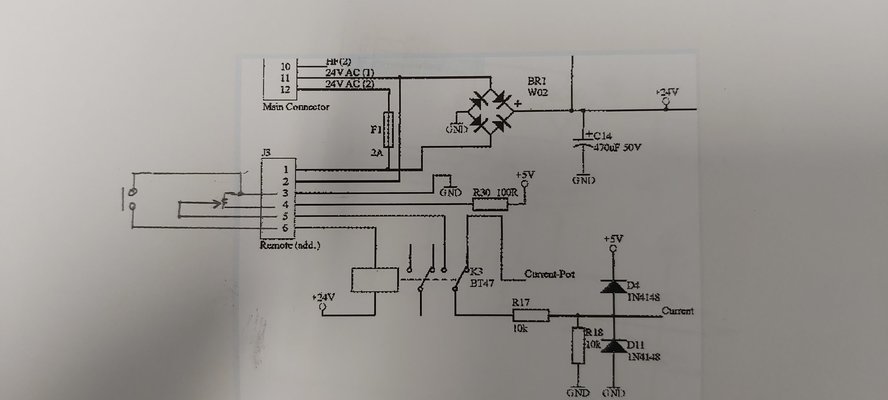
On the phone he said the 7 pins on the plug for pedal connection served the following purposes:
1: 24V supply
2: 24V supply
3: Ground
4: 5 V supply
5: Remote Demand
6: 24V feedback
7: not used
Based on this info I've pencil drawn what I think would be the correct circuit onto the plug in the wiring diagram he sent me (see pic). The bit that is throwing me is the 2x24 supply on pin 1 and 2. Anyone know what this would be for?
Is my diagram correct?
New to the forum and have read a few posts with interest regarding building your own tig pedal, which is something I'm embarking on.
I understand the concept. A potentiometer varies voltage which is sent as feedback to the PCB inside the welder and a microswitch turns the torch on.
The problem I'm having is figuring out how to wire everything to the 7pin plug on my TIG machine
I have a Newarc RT2000 and cant find diagrams for it anywhere on the web. I called Newarc up and I've had some success in getting some info including a wiring diagram for the 7 pin plug but I'm now stumped.
On the phone he said the 7 pins on the plug for pedal connection served the following purposes:
1: 24V supply
2: 24V supply
3: Ground
4: 5 V supply
5: Remote Demand
6: 24V feedback
7: not used
Based on this info I've pencil drawn what I think would be the correct circuit onto the plug in the wiring diagram he sent me (see pic). The bit that is throwing me is the 2x24 supply on pin 1 and 2. Anyone know what this would be for?
Is my diagram correct?