Yes, I think you are close to solving this!
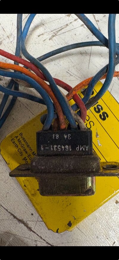
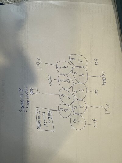
However, we need to clarify the way that DB-9 connector pins are numbered. The numbers may be moulded into the plastic, but are very small. For the female DB-9 plug on the wiring harness, the right-hand picture will apply:

Please note that the pin opposite 1 is 6, not 9.
The red wire with the ring terminal is the positive DC feed from a bolted connection at the MIG welding torch to the board at Pins 2 and 6, but it actually may connect at the positive terminal of the motor.
The negative of this DC welding output, from the choke, is a blue wire to Pin 7 of the DB-9.
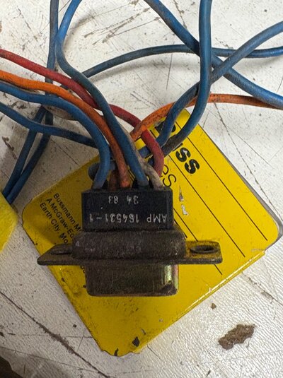
However, we need to clarify the way that DB-9 connector pins are numbered. The numbers may be moulded into the plastic, but are very small. For the female DB-9 plug on the wiring harness, the right-hand picture will apply:
Please note that the pin opposite 1 is 6, not 9.
The red wire with the ring terminal is the positive DC feed from a bolted connection at the MIG welding torch to the board at Pins 2 and 6, but it actually may connect at the positive terminal of the motor.
The negative of this DC welding output, from the choke, is a blue wire to Pin 7 of the DB-9.