


You are using an out of date browser. It may not display this or other websites correctly.
You should upgrade or use an alternative browser.
You should upgrade or use an alternative browser.
Clarke SE16C150 - pump rebuild tips
- Thread starter gasket999
- Start date


gasket999
getting there...
- Messages
- 382
- Location
- Manchester, UK
Made a fair bit of progress this weekend.
New Piston rings arrived. I only needed an oil scraper but ended buying a full set as they didn't have individual ones in stock.

So had 6 rings in total. I tried each in each of the cylinders so that I could measure the ring gaps.


I picked the four with the closest grouping and tightest gaps.
Pistons cleaned up, lightly polished and gudgeon pins reinserted (pistons were marked on disassembly and reassembled as matched sets in correct orientation)

Rings fitted

And reassembled onto the crank. Big end caps were fitted with the same bolts and thread lock was used (as per Clarke's instructions). Lots of compressor oil used on all mating surfaces prior to assembly.

I didn't have a piston ring compressor, and due to neding to slide the cylinders over both pistons I would have needed a pair or motorcycle ring sets and couldn't justify it for one job. So I cut two strips of plastic from an old paint pot and used a pair of jubilee clips to compress the rings. Worked well.

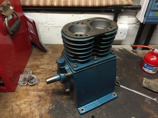
Pistons and cylinders fitted. Look good - see the 'before pics' earlier in the thread to see what a mess these were.

cylinders in place and looking good.

New Piston rings arrived. I only needed an oil scraper but ended buying a full set as they didn't have individual ones in stock.
So had 6 rings in total. I tried each in each of the cylinders so that I could measure the ring gaps.
I picked the four with the closest grouping and tightest gaps.
Pistons cleaned up, lightly polished and gudgeon pins reinserted (pistons were marked on disassembly and reassembled as matched sets in correct orientation)
Rings fitted
And reassembled onto the crank. Big end caps were fitted with the same bolts and thread lock was used (as per Clarke's instructions). Lots of compressor oil used on all mating surfaces prior to assembly.
I didn't have a piston ring compressor, and due to neding to slide the cylinders over both pistons I would have needed a pair or motorcycle ring sets and couldn't justify it for one job. So I cut two strips of plastic from an old paint pot and used a pair of jubilee clips to compress the rings. Worked well.
Pistons and cylinders fitted. Look good - see the 'before pics' earlier in the thread to see what a mess these were.
cylinders in place and looking good.
Last edited:
gasket999
getting there...
- Messages
- 382
- Location
- Manchester, UK
flywheel as found. Back was covered in very thick chalky paint. Front had the same chalky red paint but the PO had sprayed over this in black. Bless him.


cleaned up well. Will fit as-is as if I respray the compressor I'll do it as a complete assembly as per the factory.

valve plate and individual exhaust valves cleaned up and refitted

same with inlet valves

new head gasket on

valve plate on

reassembling the exhaust/aftercooler bit. The brass safety valve and reducer were removed, cleaned and refitted. All new gaskets used.


valve cover and exhaust/cooler elbow fitted

cleaned up well. Will fit as-is as if I respray the compressor I'll do it as a complete assembly as per the factory.
valve plate and individual exhaust valves cleaned up and refitted
same with inlet valves
new head gasket on
valve plate on
reassembling the exhaust/aftercooler bit. The brass safety valve and reducer were removed, cleaned and refitted. All new gaskets used.
valve cover and exhaust/cooler elbow fitted
Last edited:
gasket999
getting there...
- Messages
- 382
- Location
- Manchester, UK
new air filter housing fitted

and new element and cover


refitted back onto the tank and pipes hooked up. PO had messed with the fixing bots so any missing washers and lock-washers were replaced upon reassembly
Head bolts were torqued once the pump was on the tank - much easier to hold that way. Progressively built up to 30NM, tightening in the correct pattern. Torqued all other 13 and 15mm bolts to 25NM. There's no clarke torque specs for these but 25NM felt about right.

and new element and cover
refitted back onto the tank and pipes hooked up. PO had messed with the fixing bots so any missing washers and lock-washers were replaced upon reassembly
Head bolts were torqued once the pump was on the tank - much easier to hold that way. Progressively built up to 30NM, tightening in the correct pattern. Torqued all other 13 and 15mm bolts to 25NM. There's no clarke torque specs for these but 25NM felt about right.
Last edited:
gasket999
getting there...
- Messages
- 382
- Location
- Manchester, UK
Time to refit the flywheel. Refitted Woodruffe key and refitted flywheel - seated it with some gentle taps with the dead-blow mallet and refitted reverse-thread bolt, washer and lock washer. Torqued to 25NM.


Time to look at the motor.
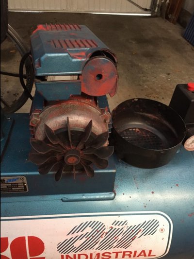
Removed fan housing (was only held on with one of four screws - will replace these). Bit of paint on the blades so I cleaned this up before refitting the cover - but no paint got near the shaft.

Refitted the cover and found some additional M4 bolts to hold the housing properly (PO had been at it again)
Time to look at the motor.
Removed fan housing (was only held on with one of four screws - will replace these). Bit of paint on the blades so I cleaned this up before refitting the cover - but no paint got near the shaft.
Refitted the cover and found some additional M4 bolts to hold the housing properly (PO had been at it again)
gasket999
getting there...
- Messages
- 382
- Location
- Manchester, UK
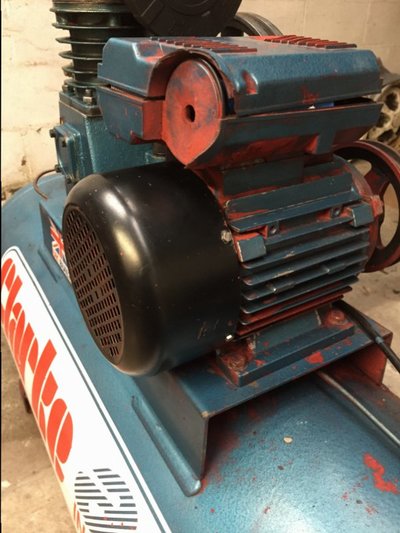
Temporarily removed the motor so I could clean paint from underneath. Would have to have loosened it anyway to refit the belt.

refitted the motor and aligned the pulleys, placing an appropriate amount of tension on the belt.

Now attention briefly turns to the motor. Remember the before pic of the capacitor box? (have a look in the earlier posts - the box was all broken, much wiring was melted and had had lots of parts chopped out of it including the terminal block and overload protection switch.
So had to start again - using wiring diagrams from Clarke and the pics posted above by helpful MM-ers. Started by stripping everything off and cleaning up the housing and wires:

remains of the broken rubbish. Capacitors will be reused.

Nice shiny new bits -a new capacitor box, cleaned up capacitors, a new HD terminal block and a new correct overload switch. Plus crimp connectors as fitted in the factory.

looks better already
refitted the motor and aligned the pulleys, placing an appropriate amount of tension on the belt.
Now attention briefly turns to the motor. Remember the before pic of the capacitor box? (have a look in the earlier posts - the box was all broken, much wiring was melted and had had lots of parts chopped out of it including the terminal block and overload protection switch.
So had to start again - using wiring diagrams from Clarke and the pics posted above by helpful MM-ers. Started by stripping everything off and cleaning up the housing and wires:
remains of the broken rubbish. Capacitors will be reused.
Nice shiny new bits -a new capacitor box, cleaned up capacitors, a new HD terminal block and a new correct overload switch. Plus crimp connectors as fitted in the factory.
looks better already

Last edited:
gasket999
getting there...
- Messages
- 382
- Location
- Manchester, UK
starting the wiring. There was enough length in the cable from the pressure switch for me to chop away any damaged cable. Clamped the main sheath and refitted the earth

Fitted various connectors, fitted the new overload switch and loosely fitted the terminal block. The neutral is the only one who's location I'm sure of at this point. Had to extend the live with a crimp connector as there wasn't enough length in the cable. Wrapped over the crimp connector in electrical tape. I may replace this whole cable from the switch to the motor in the future. No need, but I do like things to be neat.
Use a ratchet crimper, they're amazing.

Two capacitors cleaned up

PO had used a 13a plug…

Swapped this for a 32a commando socket. I have a dedicated 10mm-square cable from the CU to a 32a socket for the compressor

left the motor at this point - just loosely refitted the lid to the capacitor box. Need to speak to Clarke about the correct wiring. The diagram I have is for a slightly different iteration of this motor and want to be sure before I switch it on.
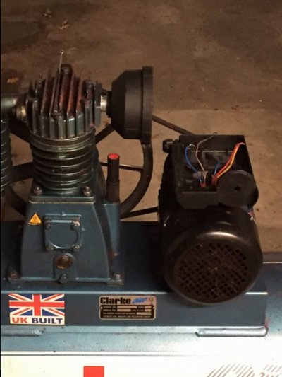
Refitted the back of the mesh guard. Span the compressor by hand - moves beautifully, definitely works - just a few spins and air starts rushing out of the (open) drain valve.

Front cover on, compressor is now fully serviced, filled with oil and (once I have the wiring diagram) it will take about 5 minutes to finish the wiring and fire her up.
She's less than 2 years old. Looks about 20-years old… and mechanically is like she's just left the factory. Wonder i there's a market for patina'd old tools that are perfect under the faded paint and scratches (like there is with old cars - ha ha).

and thats all for now folks.
Have taken lots of pics of the motor wiring, so might start another short thread to get help in coming up with a wiring diagram for next weekend if Clarke don't come through with the goods.

Fitted various connectors, fitted the new overload switch and loosely fitted the terminal block. The neutral is the only one who's location I'm sure of at this point. Had to extend the live with a crimp connector as there wasn't enough length in the cable. Wrapped over the crimp connector in electrical tape. I may replace this whole cable from the switch to the motor in the future. No need, but I do like things to be neat.
Use a ratchet crimper, they're amazing.
Two capacitors cleaned up
PO had used a 13a plug…
Swapped this for a 32a commando socket. I have a dedicated 10mm-square cable from the CU to a 32a socket for the compressor
left the motor at this point - just loosely refitted the lid to the capacitor box. Need to speak to Clarke about the correct wiring. The diagram I have is for a slightly different iteration of this motor and want to be sure before I switch it on.
Refitted the back of the mesh guard. Span the compressor by hand - moves beautifully, definitely works - just a few spins and air starts rushing out of the (open) drain valve.
Front cover on, compressor is now fully serviced, filled with oil and (once I have the wiring diagram) it will take about 5 minutes to finish the wiring and fire her up.
She's less than 2 years old. Looks about 20-years old… and mechanically is like she's just left the factory. Wonder i there's a market for patina'd old tools that are perfect under the faded paint and scratches (like there is with old cars - ha ha).
and thats all for now folks.
Have taken lots of pics of the motor wiring, so might start another short thread to get help in coming up with a wiring diagram for next weekend if Clarke don't come through with the goods.
gasket999
getting there...
- Messages
- 382
- Location
- Manchester, UK
go into your local Machine mart store and ask iff you can just lift the motor lid on the display model and take a couple of pics...cant see any harm done.
Great minds and all that… I did. My local MM were great, they let me look under the cover and even dug another loose motor out of the stores to check that one. Unfortunately both had the same wiring as MM289's motor above (and the clarke wiring diagram) and is slightly different. The groupings of the wires coming out of the motor are the problem parts - there's two on mine - Brown, Blue, Black on one side and blue, red, yellow on the other.
The one in MM and the wiring diagram and MM289's all have 4 wires: brown, yellow, black and grey on one side and two wires, both blue, on the other.
If you are not able to get the correct wiring diagram I would suggest that you bring the motor to someone who can connect it up for you. I would suggest you look in yellow pages for your nearest motor rewinders. You could try an electrician but unless they do plant work a lot would be clueless on motor wiring. If I was near you I could probably help connect it up.
If you feel confident you could have a go at identifying the wires coming out of the motor - you'll need to do this anyway even with the proper wiring diagram as it may not have the correct wiring colours or no colours at all, most just use u1,u2,v1,v2,etc.
You will need a multi-meter to identify 3 pairs of wires by checking the resistance between each wire. One pair will have very low resistance, nearly zero, these should be for the centrifugal switch. The pair with the highest resistance will be the start windings, the other pair will have a slightly lower restistance, these are the run windings. There are different ways of connecting these up, this is why you really need the correct winding diagram for this motor. Here's one example of how they can be connected.
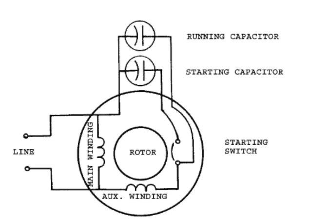
That's assuming it has a centrifugal switch otherwise I don't know why it has 6 wires. If you can't get any diagram from clarke you could try the motor manufacturers. Single phase motor wiring can be a nightmare as there are so many ways of doing it.
Do you know which capacitor is which? The start should be quite a high value and the run much lower but that's not always the case.
If you feel confident you could have a go at identifying the wires coming out of the motor - you'll need to do this anyway even with the proper wiring diagram as it may not have the correct wiring colours or no colours at all, most just use u1,u2,v1,v2,etc.
You will need a multi-meter to identify 3 pairs of wires by checking the resistance between each wire. One pair will have very low resistance, nearly zero, these should be for the centrifugal switch. The pair with the highest resistance will be the start windings, the other pair will have a slightly lower restistance, these are the run windings. There are different ways of connecting these up, this is why you really need the correct winding diagram for this motor. Here's one example of how they can be connected.
That's assuming it has a centrifugal switch otherwise I don't know why it has 6 wires. If you can't get any diagram from clarke you could try the motor manufacturers. Single phase motor wiring can be a nightmare as there are so many ways of doing it.
Do you know which capacitor is which? The start should be quite a high value and the run much lower but that's not always the case.
gasket999
getting there...
- Messages
- 382
- Location
- Manchester, UK
Thanks very much for the above. I still haven't tried to connect it all up - frustrating as its 5 mins away from being finished.
I'll have to get a multimeter, learn how to use it and start to identify the wires - only 6 to work out.
I'll have to get a multimeter, learn how to use it and start to identify the wires - only 6 to work out.
gasket999
getting there...
- Messages
- 382
- Location
- Manchester, UK
Oh and yes - the wiring diagram from Clarke, while from the wrong motor, is close - so it shows me where on the terminal block to connect the live, neutral and Earth as well as the overload switch and each of the two capacitors. It's the six wires from the motor that are confusing
gasket999
getting there...
- Messages
- 382
- Location
- Manchester, UK
Well folks, its been a while.
I got lucky and found a picture of the same motor online. By cross referencing these motor photos with the wiring diagrams sent from Clarke I was able to identify the wires.
Here is the diagram I've drawn up

If you check it against the nearest Clarke wiring diagram shown earlier in the thread ("motor 6430466 3-2-1 230v.pdf"), you will see the differences are just colour and grouping. It is wired up exactly as it would have been from the factory (albei with a better quality terminal block and stronger connections).
On the Clarke diagram there was two groups of wires coming out of the motor (Brown/Yellow/Black/Grey on one side and Blue/Blue on the other) on mine there were two groups of three (Black/Blue/Brown and Red/Yellow/Blue).
These correspond to:
My specific motor:.………Clarke generic wiring diagram:
Red……………………………….Brown
Yellow…………………………..Black
Blue (RH Group)…………..Blue (2)
Brown…………………………..Grey
Blue (LH Group)…………..Blue (1)
Black…………………………...Yellow
The differences according to Clarke are down to their motor manufacturer constantly changing the colours of the wires.
Thanks ever so much for the help with the wiring. The tip on identifying the pairs was a good one - I don't have a multimeter - but a battery, a bulb and some wire let me pair up the wires at least.
But (drum roll please….) It all works perfectly, and after moving the brass link bars to the alternate position the pump is being driven in the correct rotation too.
Here's the finished capacitor box:

Quite a difference from where we started:

I got lucky and found a picture of the same motor online. By cross referencing these motor photos with the wiring diagrams sent from Clarke I was able to identify the wires.
Here is the diagram I've drawn up
If you check it against the nearest Clarke wiring diagram shown earlier in the thread ("motor 6430466 3-2-1 230v.pdf"), you will see the differences are just colour and grouping. It is wired up exactly as it would have been from the factory (albei with a better quality terminal block and stronger connections).
On the Clarke diagram there was two groups of wires coming out of the motor (Brown/Yellow/Black/Grey on one side and Blue/Blue on the other) on mine there were two groups of three (Black/Blue/Brown and Red/Yellow/Blue).
These correspond to:
My specific motor:.………Clarke generic wiring diagram:
Red……………………………….Brown
Yellow…………………………..Black
Blue (RH Group)…………..Blue (2)
Brown…………………………..Grey
Blue (LH Group)…………..Blue (1)
Black…………………………...Yellow
The differences according to Clarke are down to their motor manufacturer constantly changing the colours of the wires.
Thanks ever so much for the help with the wiring. The tip on identifying the pairs was a good one - I don't have a multimeter - but a battery, a bulb and some wire let me pair up the wires at least.
But (drum roll please….) It all works perfectly, and after moving the brass link bars to the alternate position the pump is being driven in the correct rotation too.
Here's the finished capacitor box:
Quite a difference from where we started:
gasket999
getting there...
- Messages
- 382
- Location
- Manchester, UK
So the compressor works!!
Pump runs very well (and much quieter than the direct drive units I'm used to).
The little blow-out valve on the pump exhaust is sticking open despite being cleaned and refitted, so I'll have to have a look at that before I can take it up to pressure.
Pump runs very well (and much quieter than the direct drive units I'm used to).
The little blow-out valve on the pump exhaust is sticking open despite being cleaned and refitted, so I'll have to have a look at that before I can take it up to pressure.


